Author Archives: Therm

Honeywell CT410B Thermostats Installation Instructions

above.

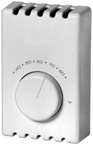
Resideo T410 line voltage electric heat thermostat with temperature setting knob
T410 electric heat thermostat.

Specifications

  • Models: T410A provides single-line break. T410B provides double-line break.
  • Temperature range: 40°F to 80°F (4°C to 27°C)
  • Electrical ratings: 60 Hz noninductive; 22A at 120-240 Vac; 19A at 277 Vac

Safety notices

WARNING — Electric shock hazard. This thermostat is a line voltage control (120 Volts to 277 Volts.) Do not install it if you are not completely familiar with house wiring. If handled improperly, there can be risk of a 120 Volt to 277 Volt electric shock hazard, which may cause serious injury or death.

Mercury notice. If this control is replacing a control that contains mercury in a sealed tube, do not place you old control in the trash. Dispose of properly.

Contact you local waste management authority for instruction regarding recycling and the proper disposal of a old control.

1. Preparation

  1. Proper installation of your Resideo thermostat will occur if you follow these instructions STEP-BY-STEP. It is recommended that as you read, understand and complete each step, you check it off with pencil or pen.
  2. Check thermostat suitability for your home system by reviewing the ratings listed on this page.
  3. Make certain that your heating system is working, especially if it has been inoperative for a length of time. If the system does not work, contact your local electrician for assistance.
  4. Carefully unpack your new thermostat. To avoid damage to the sensing element, do NOT remove the thermostat cover until wiring has been completed.
  5. Save packages of screws, instructions, receipt and proof-of-purchase.

2. Remove Old Thermostat

WARNING — Electric shock hazard. Begin by turning off power to the heating circuit at the main service panel.

  1. Remove cover of old thermostat. Cover normally snaps off when pulled firmly from the bottom. If it resists, check for a screw that locks the cover.
  2. Loosen screws holding thermostat base to outlet box and lift away.
  3. Disconnect wires from old thermostat. As you disconnect each wire, tape the end and label it with the letter of the terminal designation to make reconnection to new thermostat easier.
  4. Check the old insulation for cracks, nicks or fraying, and apply high quality plastic tape where necessary for adequate insulation.
  5. Retain the old thermostat for reference purposes and until your new thermostat is functioning smoothly.

3. Wire and Mount New Thermostat

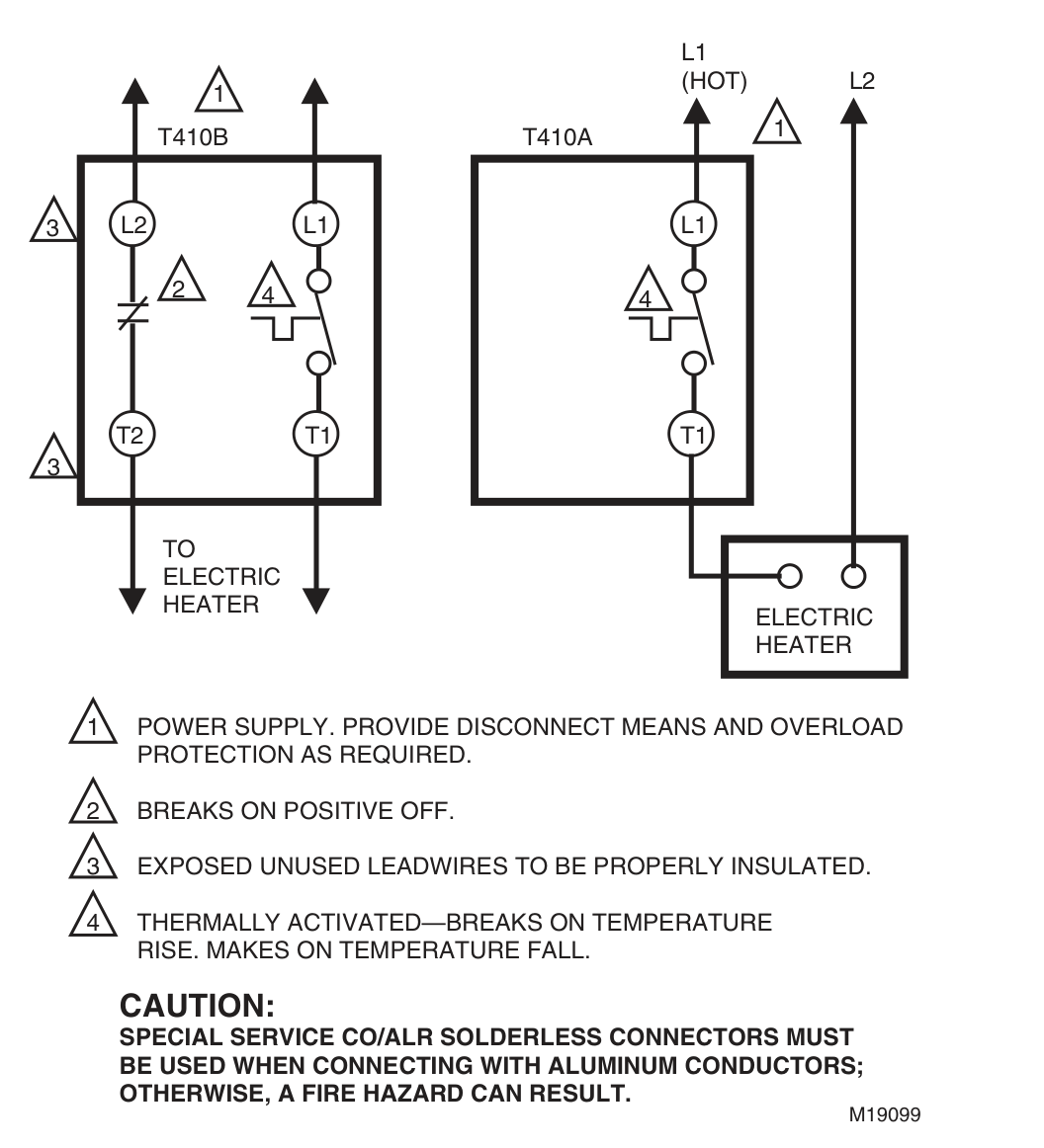
  1. Connect wires to the thermostat as shown in the applicable wiring diagram.
  2. Remove thermostat cover by grasping the top and bottom ends with fingers, and pulling outward.
  3. Push the wires into the outlet box, and insert the thermostat into the box for mounting by pushing against top and bottom of the thermostat base.

Important: Do not press on setting knob.

  1. Secure the thermostat to the box with the two captive mounting screws provided.
  2. Replace thermostat cover.
  3. Set knob to desired room temperature.

Important: Rough handling or strong pressure can damage knob or sensing element, and change calibration.

Wiring diagrams for T410B double-line break and T410A single-line break thermostats, with legend notes and caution about aluminum conductors
Fig. 1. T410B (double-line break, left) and T410A (single-line break, right) wiring diagrams.
Diagram notes (text version)
  • Power supply. Provide disconnect means and overload protection as required.
  • Breaks on positive off.
  • Exposed unused leadwires to be properly insulated.
  • Thermally activated—breaks on temperature rise. Makes on temperature fall.

Caution: Special service CO/ALR solderless connectors must be used when connecting with aluminum conductors; otherwise, a fire hazard can result.

4. Check Out Thermostat

  1. Turn on the power to the heating system.
  2. Turn setting knob all the way clockwise; listen for clicking sound as switch makes contact. Electric heater should begin operation.
  3. Turn knob all the way counterclockwise; listen for clicking sound as switch breaks contact. Electric heater should shut off.

5. Setting Thermostat

  1. Begin with knob to the desired setting (typically 70°F [20°C] on the scale).
  2. If this setting is not satisfactory after at least two hours of operation, turn setting knob upscale to raise the temperature, or downscale to lower the temperature. Move knob only a degree each time.

6. Troubleshooting

Your Resideo thermostat requires little or no attention. Most problems can generally be traced to the following:

Table 1. Troubleshooting.

Symptom Checkout Action
No heat. Make sure power is on at main service panel. Turn the temperature setting knob fully clockwise. Heater should start to warm up within two minutes. If not, contact qualified electrician to check thermostat and heater.
Improper connections to thermostat. With power to circuit OFF, tighten all wiring connections. Repair any frayed or broken wires.
Other. Contact a qualified electrician for assistance.
Heater never turns off. Turn temperature setting knob fully counterclockwise. Heater should start to cool within minutes. If not, turn off power at the main service panel, and contact qualified electrician.
Thermostat setting and thermometer reading disagree. Thermostat affected by drafts or radiant heat. Contact electrician to change the location. The thermostat should be about 5 ft (1.5m) above the floor and on an inside wall.

1-Year Limited Warranty

Resideo warrants this product, excluding battery, to be free from defects in workmanship or materials, under normal use and service, for a period of one (1) years from the date of first purchase by the original purchaser. If at any time during the warranty period the product is determined to be defective due to workmanship or materials, Resideo shall repair or replace it (at Resideo’s option).

If the product is defective,

  1. return it, with a bill of sale or other dated proof of purchase, to the place from which you purchased it; or
  2. call Resideo Customer Care at 1-800-468-1502. Customer Care will make the determination whether the product should be returned to the following address: Resideo Return Goods, 1985 Douglas Dr. N., Golden Valley, MN 55422, or whether a replacement product can be sent to you.

This warranty does not cover removal or reinstallation costs. This warranty shall not apply if it is shown by Resideo that the defect was caused by damage which occurred while the product was in the possession of a consumer.

Resideo’s sole responsibility shall be to repair or replace the product within the terms stated above. RESIDEO SHALL NOT BE LIABLE FOR ANY LOSS OR DAMAGE OF ANY KIND, INCLUDING ANY INCIDENTAL OR CONSEQUENTIAL DAMAGES RESULTING, DIRECTLY OR INDIRECTLY, FROM ANY BREACH OF ANY WARRANTY, EXPRESS OR IMPLIED, OR ANY OTHER FAILURE OF THIS PRODUCT.

Some states do not allow the exclusion or limitation of incidental or consequential damages, so this limitation may not apply to you.

THIS WARRANTY IS THE ONLY EXPRESS WARRANTY RESIDEO MAKES ON THIS PRODUCT. THE DURATION OF ANY IMPLIED WARRANTIES, INCLUDING THE WARRANTIES OF MERCHANTABILITY AND FITNESS FOR A PARTICULAR PURPOSE, IS HEREBY LIMITED TO THE ONE YEAR DURATION OF THIS WARRANTY. Some states do not allow limitations on how long an implied warranty lasts, so the above limitation may not apply to you.

This warranty gives you specific legal rights, and you may have other rights which vary from state to state. If you have any questions concerning this warranty, please write Resideo Customer Care, 1985 Douglas Dr, Golden Valley, MN 55422 or call 1-800-468-1502.

Document information

This product is manufactured by Resideo Technologies, Inc., Golden Valley, MN, 1-800-468-1502. ©2019 Resideo Technologies, Inc. The Honeywell Home trademark is used under license from Honeywell International Inc. All rights reserved. www.resideo.com

Resideo Inc., 1985 Douglas Drive North, Golden Valley, MN 55422

69-1562—02   M.S. Rev. 07-19  |  Printed in United States

Honeywell RTH7500D Programmable Thermostat Owner’s Manual

The Honeywell RTH7500D Programmable Thermostat Owner’s Manual is a 64-page booklet, document 69-1730, dated 2004. It carries the installation steps on pages 3 to 38 and the operating instructions on pages 39 to 61, then customer assistance and the warranty. This page works through the operating half in the order an owner meets it. It starts with the display and the buttons, then the schedule, the holds, the maintenance reminders and the fourteen fault entries the booklet prints. Wiring and the installer setup numbers are kept as reference tables further down.

Download the Honeywell RTH7500D Owner’s Manual (PDF)

Skip to PDF content

Honeywell TH8110U1003 VisionPro Thermostat Operating Manual

Honeywell TH8110U1003 VisionPro Thermostat Operating Manual

This Honeywell TH8110U1003 VisionPro Thermostat Operating Manual guide is for the touchscreen that arrived pre-programmed and only needs a clock set. Everything below is quoted from the 32-page PDF, with the page number attached so you can check it.

Table of Contents

What Is the TH8110U1003?

Plain answer: a touchscreen thermostat for a single-stage system, sold as part of the VisionPro TH8000 Series. The manual calls it “the world’s most advanced, easy-to-use thermostat” (page 2).

One booklet covers three models, and the differences matter. Page 1 prints the list, “This manual covers the following models”:

  • “TH8110U: For 1 Heat/1 Cool systems”
  • “TH8320U: For up to 3 Heat/2 Cool systems”
  • “TH8321U: For up to 3 Heat/2 Cool systems with dehumidification”

The model number decides what the extra menu options do; to find it, “Pull thermostat from wallplate and turn over to find model number” (page 1).

Page 1 also warns: “Never use sharp instruments, such as a pencil or pen, to press touchscreen keys.”

Controls at a Glance

Page 4 prints the screen with every key labelled, and the captions under it say what each key does:

Touchscreen keys, from the quick reference on page 4
KeyWhat the manual says it does
SCHED“Press to set program schedule (see page 11)”
HOLD“Press to override program schedule (see pages 12-14)”
CLOCK“Press to set clock (see page 6)”
SCREEN“Press to lock keypad for 30 seconds to clean screen (see page 17)”
MORE“Press for more options (select models only)”
FAN“Press to select fan operation (see page 7)”
SYSTEM“Press to select system type (see page 8)”

Page 5 lists the status line: “Cool On: Cooling system is activated”, “Heat On: Heating system is activated” and “Recovery” — for when “Adaptive Intelligent Recovery in effect (see page 15)”, the feature that lets the thermostat “learn” how long the furnace and air conditioner take “to reach programmed temperature settings”. Heat running early for a wake-up isn’t a bug.

Clock, Fan and System Settings

Set the clock first. Page 6: “To set the current time display, press CLOCK, then press” the up or down arrow, and DONE saves. The note that separates it from a cheap dial: “The real-time clock should never require adjustment since it automatically updates for daylight savings time, and stores all date/time information”. The weekday is set in the advanced functions.

Fan has three modes, and page 7 defines them exactly:

  • “On: Fan is always on.”
  • “Auto: Fan runs only when the heating or cooling system is on.”
  • “Circ: Fan runs randomly, about 35% of the time, not counting any run time with the heating or cooling system.”

Two fine points from that page: “If a fan schedule is programmed, “Auto” will run the fan schedule”, and a forced fan stays put — “the setting you select will remain active until you press FAN again to select Auto”.

Page 8 gives SYSTEM its positions: “Heat: Thermostat controls only the heating system.” “Cool: Thermostat controls only the cooling system.” “Off: Heating and cooling systems are off.” “Auto: Thermostat automatically selects heating or cooling depending on the indoor temperature.” A fifth, Em Heat, is flagged “Select models only”, and its result is blunt: “Compressor is locked out.”

Programming the Schedule

The Honeywell VisionPro thermostat programming instructions begin on page 9, under “Save money by setting program schedules”, which defines the four periods by what you’re doing in them:

  • Wake — “Set to the time you awaken and the temperature you want during the morning, until you leave for the day.”
  • Leave — “Set to the time you leave home and the temperature you want while you are away (usually an energy-saving level).”
  • Return — “Set to the time you return home and the temperature you want during the evening, until bedtime.”
  • Sleep — “Set to the time you go to bed and the temperature you want overnight (usually an energy-saving level).”

The factory schedule assumes a conventional day. Page 3 states the presets in one line: “energy-saving levels while you’re at work or asleep (assumes you wake at 6 am, leave at 8 am, return at 6 pm and go to bed at 10 pm)”.

Adjusting a period

Page 11’s steps, in the manual’s own words:

  1. “Press SCHED, then EDIT.”
  2. “Press day buttons (MON-SUN) to select day(s).”
  3. Set that period’s time and its heat and cool temperatures with the up or down arrow.
  4. “Press other time periods (LEAVE, RETURN, SLEEP) to set time and temperatures for each.”
  5. Press DONE to save, or CANCEL to leave without saving changes.

Two helpers: “You can press CANCEL PERIOD to eliminate any unwanted time period”, and “Press FAN to customize fan settings for any time period (see page 7)”. The day buttons copy one day onto others — the screen prints “OK TO PICK MULTIPLE DAYS” above them. Want two periods instead of four? Advanced function 0540 switches between “Two program periods (Wake, Sleep)” and “Four program periods (Wake, Leave, Return, Sleep)” (page 25).

Temporary, Permanent and Vacation Holds

Temporary. Press the up or down arrow: “This will temporarily override the temperature setting for the current time period.” When the timer expires or you press CANCEL or SCHED, “the program schedule will resume and set the temperature to the level you’ve programmed”.

Permanent. “Press HOLD to permanently adjust the temperature. This will turn off the program schedule.” Page 13: what you set “will be maintained 24 hours a day until you manually change it or press CANCEL (or SCHED) to cancel “Hold” and resume the program schedule.”

Vacation. Page 14 suspends the schedule for a counted run of days: set a temperature and the resume time, then “Press HOLD twice” and pick the count. “Whatever temperature you set will be maintained 24 hours a day for the number of days you select. After this number of days have elapsed, the previously programmed schedule will resume at the time you set.” Back early? CANCEL or SCHED resumes it.

Screen Lock, Cleaning and Humidity

Page 16 covers tampering: “To prevent tampering, the screen can be partially or fully locked.” In partial lock, “the screen displays SCREEN LOCKED for several seconds if a locked key is pressed”, and any unlocked key clears it while that message shows. Full lock is absolute — “When the screen is fully locked, no keys function.” Both come from advanced function 0670 (page 25).

Cleaning has its own key: “Press SCREEN to lock the screen for cleaning. The screen will remain locked for 30 seconds so you can clean the screen without changing any settings” (page 17). On liquids: “Do not spray any liquid directly on the thermostat. Spray liquids onto a cloth, then use the damp cloth to clean the screen.”

Humidity is a select-models feature. “Select models can display the current indoor humidity level” (page 18), and “When humidity increases, the thermostat runs the air conditioner longer to reduce humidity” (page 19). With an outdoor sensor fitted, “the outdoor temperature is shown instead of the humidity level. Press MORE to display the humidity level.”

Advanced Functions

Entering setup is a two-key trick, not a menu button. Page 21: “1. Press SYSTEM.” then “2. Press and hold blank center key until the display changes.” The blank centre key is the space in the middle of the screen. The Honeywell TH8000 series advanced functions a homeowner needs:

Advanced functions quoted from pages 22-25
FunctionNameSettings in the manual
0160“Program schedule on/off”“0 Program schedule is off. Thermostat is non-programmable.” / “4 Program schedule is on (7-day programmable).”
0540“Program schedule periods”“2 Two program periods (Wake, Sleep)” / “4 Four program periods (Wake, Leave, Return, Sleep)”
0320“Temperature format (°F/°C)”“0 Fahrenheit” / “1 Celsius”
0670“Screen lock”“0 Screen is unlocked (fully functional)” / “2 Screen is fully locked”
0500“Furnace filter change reminder”“0 Off (no reminder to change furnace filter)” through “6 Reminder after 365-day run time (about 3 years)”
0510“Humidifier pad change reminder”“1 Reminder after 3 months” / “2 Reminder after 6 months” / “3 Reminder after 1 year”
0520“UV lamp change reminder”“1 Reminder after 1 year”
0120-0150Year, month and date settingsFour separate functions: the two year digits, month (1-12) and date (1-31)
0330“Daylight savings time on/off”“The thermostat is pre-programmed to automatically adjust to daylight savings time.”

Every reminder alert clears the same way: “Press RESET to cancel the alert”.

Batteries and Reset

Page 20 opens with the fact that surprises most owners: “Batteries are optional (to provide backup power) if your thermostat was wired to run on AC power when installed.” When the warning starts, “Install fresh batteries immediately when the LO BATT warning begins flashing.” Even without one, the standing advice is to “replace batteries once a year, or before leaving home for more than a month”, and TH8110U1003 battery replacement takes “3 fresh AAA alkaline batteries”.

There is no factory reset button in this document, so how to reset Honeywell VisionPro thermostat settings comes down to the levers the manual does give. To clear the schedule rather than the power, use function 0160: “0 Program schedule is off. Thermostat is non-programmable.” / “4 Program schedule is on (7-day programmable).” Because the clock “stores all date/time information”, a battery swap shouldn’t cost you the schedule.

In Case of Difficulty

For TH8110U1003 troubleshooting, page 26 opens with “If you have difficulty with your thermostat, please try the following suggestions. Most problems can be corrected quickly and easily.” and names five symptoms. Here is the manual’s own list, with only what this PDF copy prints as readable text:

The manual’s “In case of difficulty” symptoms, pages 26-27
SymptomWhat this copy of the manual reads
“Display is blank”Fixes are in the scrambled block; the readable tail says “batteries are correctly installed (see page 20).”
“No response to key presses (or temperature will not change)”Listed on page 26; read the bullets under it in your own copy.
“Backlight is dim”Listed on page 26, followed by the same readable “batteries are correctly installed (see page 20).”
“Heating or cooling system does not respond”Press SYSTEM once each way: “Make sure the temperature is set higher than the Inside temperature.” / “Make sure the temperature is set lower than the Inside temperature.”
“Heating or cooling system does not respond”If “Wait” is displayed, the readable tail gives “5 minutes for the system to restart safely, without damaging the compressor (see page 15).”
“Display shows Fan Auto and On or Auto and Circ at the same time”“If Auto and On is shown, the fan is scheduled for “On” during this period (see page 7).”

That gap is the honest limitation of this run: several pages of this PDF — the feature list on page 2, the preset temperatures on page 10 and most of the troubleshooting on page 26 — use a subset font with no usable text mapping, so they extract as scrambled glyphs. The symptom names above survived because they print in a normal font; the sentences under them did not. For those rows the paper manual is the authority.

Specifications

  • Document: Operating Manual, VisionPRO TH8000 Series Touchscreen Programmable Thermostat, number 69-1894EFS-03, 32 pages, © 2011 Honeywell International Inc.
  • Schedule: four periods a day, weekday and weekend settings, “7-day programmable” through function 0160.
  • Warranty: page 29 heads a “5-year limited warranty”, and the readable exclusion says “This warranty does not cover removal or reinstallation costs.”
  • Support: “call Honeywell Customer Care toll-free at 1-800-468-1502”.

FAQ

Can the TH8110U1003 run two stages of heating?

Not per this document, which assigns it one stage each way: “TH8110U: For 1 Heat/1 Cool systems”. The models in the same booklet that handle more are TH8320U and TH8321U, “For up to 3 Heat/2 Cool systems”.

Why does the screen say Wait after I turn the cooling on?

Compressor protection, which page 15 defines as a delay rather than a fault: “This feature forces the compressor to wait a few minutes before restarting, to prevent equipment damage.” Page 27 gives the number: “5 minutes for the system to restart safely, without damaging the compressor”.

Is there a TH8110U1003 wiring diagram in this manual?

No. This operating manual runs from clock setting to humidity control with no terminal chart; the only wiring language here is that the thermostat may have been “wired to run on AC power when installed”.

Does the TH8110U1003 work with an app?

The document never says so. Across all 32 pages there is no mention of Wi-Fi, a network, an app or a portal — your TH8110U1003 VisionPro manual PDF describes keypad-only operation.

What if the display goes blank?

Page 26 lists “Display is blank” first, and its readable fragment points at power: “batteries are correctly installed (see page 20).” The rest of that block is in the pages this copy can’t render as text, so confirm against the paper manual.

Honeywell RTH7400D Programmable Thermostat OWNER's GUIDE

Honeywell RTH7400D Programmable Thermostat OWNER’s GUIDE

The Honeywell RTH7400D Programmable Thermostat Owner’s Guide is a 64-page booklet, document 69-1726-1, dated 08-04 on the back cover. It covers the whole life of the unit in one file. Installation runs from page 3 to page 26, the installer setup menu from page 27 to page 38, and operation from page 39 to page 61. This page follows that booklet and quotes its wording where the wording decides how a step works.

Download the Honeywell RTH7400D Owner’s Guide (PDF)

Download Honeywell RTH7400D Programmable Thermostat Owner’s Guide (PDF)

Table of Contents

What the Guide Covers

The contents page lists twelve headings with their page numbers. The file runs straight through in English with no second language, so the printed numbers and the PDF page numbers are the same throughout.

Section Pages
Prepare for Installation 3
Follow Important Instructions 5
Remove Old Thermostat 6
Follow Special Instructions 7
Label Old Thermostat Wires 10
Mount New Wallplate to Wall 11
Connect Wires to New Wallplate 15
Install Batteries 23
Attach New Thermostat to Wallplate 24
Configure Installer Setup 26
Customer Assistance 62
Limited One-Year Warranty 63

Page 1 states the electrical scope in one sentence: the thermostat provides electronic control of “24 Vac heating and cooling systems or 750 mV heating systems.” No other voltage is mentioned anywhere in the booklet.

One numbering detail explains an apparent gap. The contents page puts Configure Installer Setup at 26, while the numbered step itself opens on page 27, because page 26 finishes the calendar step.

What Comes in the Box

Step 1 asks you to check six items before starting. The guide names them in the parts drawing on page 3:

  • Wallplate
  • Thermostat
  • Mounting screws (2) and wall anchors (2)
  • Owner’s guide
  • Wire labels
  • Caution card

If any of them is missing, the instruction is to call Honeywell Customer Care at 1-800-468-1502 before returning the thermostat to the store. The same page warns to turn off power at the furnace or at the fuse and circuit breaker panel before you begin.

The tool list on page 4 is short and specific:

  • Two AA alkaline batteries
  • No. 2 Phillips screwdriver and standard pocket screwdriver
  • Drill
  • Drill bit, 3/16 in. for drywall and 7/32 in. for plaster
  • Level (optional)
  • Hammer
  • Pencil
  • Electrical tape

The bit sizes are worth reading twice: 3/16 in. for drywall and 7/32 in. for plaster, with the plaster figure repeated again in the mounting step on page 14.

Before You Touch the Wires

Step 2 is a single rule: do not connect the wires to the new thermostat based on wire colour, because damage can occur to the heating or cooling system. The guide gives the alternative in the same paragraph: the enclosed wire labels mark the wires connected to the old thermostat, and those labels are what the new connections follow.

Step 3 removes the old unit. Power goes off first, at the system or at the fuse and circuit breaker panel. Then the cover comes off, and the old thermostat comes off the wall or wallplate with the wires left in place. Page 6 adds a mercury notice: a thermostat with mercury in a sealed tube does not go in the trash, and your local waste management authority has the recycling and disposal instructions.

The C and C1 wire rules

Step 4 handles the wires that are easy to get wrong. Page 7 gives the two-wire case and page 8 gives the one-wire case:

  • Two C and C1 wires on the old thermostat: do not connect them to the new thermostat. Disconnect them, keep them from touching each other or any other wire, and wrap the bare end of each one separately with electrical tape.
  • One C or C1 wire: connect that wire to C on the new thermostat.
  • Wires not connected to the old thermostat: do not connect them to the new thermostat, and wrap their ends with electrical tape.

Step 5 labels each wire as it is disconnected, using the tags supplied in the box. The page adds a practical warning: do not let the wires fall into the wall opening once they are free.

Mounting the Wallplate

Step 6 is seven numbered moves across pages 11 to 14. Separate the wallplate from the thermostat, pass the labeled wires through the wire hole on the wallplate, then position it with the arrow pointing up.

The level is used for appearance only, and the guide says so in brackets. Mark the two mounting holes with a pencil, move the wallplate aside, and drill at the marks: 3/16 in. for drywall, 7/32 in. for plaster. Tap the wall anchors in until they sit even with the wall surface, set the wallplate over them, insert the two screws, check the level if you want, and tighten.

Wiring: Conventional and Heat Pump

Step 7 starts with a choice rather than a connection. Standard heating and cooling systems use the conventional letter designations. Heat pump systems use the heat pump designations. The guide points to the system-type table on page 30 when you are not sure which one you have.

The jumper between Rc and R

Two rules cover the metal jumper wire on the terminal block:

  • If wires are to be connected to both Rc and R, loosen both screw terminals and remove the jumper.
  • If only one of the two is to be connected, leave the jumper in place.

Wires go into the holes on the side of the terminal block that match the letter designations, and the screws are tightened afterwards. One limit applies to the whole block: do not connect more than one wire to each terminal.

Conventional systems

Page 18 prints the letter comparison for a conventional system. Each row shows a terminal on the new thermostat and the letters that may appear on the labeled wires from the old one.

Terminal on the new thermostat Possible letter on the labeled wire
RC RC or R
R R or RH, 4, V
W W or W1, H
Y Y or Y1, M
G G or F
C C or C1, X, B
Y2 Y2
W2 W2

Four numbered notes follow that chart. They are printed on page 19, and the numbers match the triangles in the drawing:

  1. If wires go to both RC and R, remove the jumper between them. If only one of the two is used, leave the jumper in place.
  2. If the old thermostat had wires on both R and RH, remove the jumper on the new one. Connect the old R to the new RC and the old RH to the new R.
  3. If two C and C1 wires were connected to the old thermostat, tape each bare end separately and do not use them.
  4. If one C or C1 wire was connected, it goes to the C designation on the new thermostat.

Heat pump systems

Page 20 prints the equivalent chart for a heat pump. This one has nine positions, one more than the conventional block.

Terminal on the new thermostat Possible letter on the labeled wire
RC VR or V or R
R No wire shown; the jumper stays in place
O/B H or B, O
Y Y1 or M or Y
G F or G
C X or B, C
L F or L
E X2 or X, E
AUX AUX, W1, W or W2

On the heat pump chart the R position carries no wire of its own. The drawing leaves the jumper between RC and R in place, and the first note on page 21 states that instruction directly. The other three notes cover cases that need a decision before wiring continues:

  • If the old thermostat had separate wires on both V and VR, some system modification is required. Call your local heating and cooling contractor for assistance.
  • If the old thermostat had wires on both O and B, attach the B wire to the C designation on the new thermostat. If another wire is already matched to C, contact Honeywell.
  • If the old thermostat had wires on W1, Y1 and W2, some system modification is required. Call your local heating and cooling contractor for assistance.

Step 7 closes by pushing excess wire back into the wall opening and keeping the wires inside the shaded area marked on the drawing.

Batteries and Mounting the Thermostat

Two fresh AA alkaline batteries go on the back of the thermostat, in the holder marked on the casing. The guide then asks for one more move that is easy to miss: remove the tab labeled “Remove during installation” in the lower right corner of the thermostat back.

Mounting is two steps and a power check. Align the screw blocks with the pins on the back of the thermostat, then push the thermostat straight onto the wallplate until it snaps into place. Turn the power back on at the system or at the fuse and circuit breaker panel. If the wires interfere with mounting, push the excess back into the wall opening.

Setting the Calendar and Clock

Page 25 states the memory behaviour: once the calendar is set, the thermostat keeps the current time and day in memory for up to ten years under normal use. The calendar is the first screen shown when the unit is powered for the first time.

  1. Use the Up or Down arrow to set the Month.
  2. Press Next to advance to the Date.
  3. Use the Up or Down arrow to set the Date.
  4. Press Next to advance to the Year.
  5. Use the Up or Down arrow to set the Year.
  6. Press Done to advance to the Time.
  7. Use the Up or Down arrow to set the Time.
  8. Press Done again to reach the home screen.

The clock has its own path once the unit is running. Press Clock & More, set the time with the arrows, and press Done. A footnote on page 48 adds that the day of the week should already be correct, and points back to the installer setup section if it is not.

System and Fan Settings

The three buttons under the display carry the everyday settings. System & Fan selects Heat, Off, Cool and Em Heat, and also selects Fan Auto or On. Schedule selects the programming mode. Clock & More selects time and furnace filter information. The two arrow buttons raise or lower the temperature setting, and in other screens they make selections.

Heat, Off, Cool and Em Heat

  • Heat: the thermostat controls the heating system.
  • Off: heating and cooling systems are both off.
  • Cool: the thermostat controls the cooling system.
  • Em. Heat: available on heat pump systems with auxiliary heat. The thermostat controls emergency heat and auxiliary heat if needed, and the heat pump compressor is not operational.

Page 41 prints a caution in the system settings section. It carries an equipment damage hazard and warns that air conditioning compressor damage is possible. It also states that the cooling system should not be operated when the outdoor temperature is below 50°F (10°C).

Fan Auto and On

Press System & Fan, then press the Fan button to choose between two modes. Auto is the setting the guide calls normal for most homes, and the fan runs only when the heating or cooling system is on. On keeps the fan running continuously, for improved air circulation or for more efficient air cleaning.

Installer Setup Numbers

Step 11 is the menu that tells the thermostat what equipment it is connected to. The entry gesture uses two different presses, and the order matters:

  1. Press and release the System button.
  2. Press and hold the center button for approximately five seconds, until the screen changes.
  3. Release the center button when the display matches the drawing on page 28.

Inside the menu, the arrows change the setting, Next advances to the next installer setup number, Done exits and saves, and Go Back returns to the last one. The number sits on the left of the display and the selected value on the right.

Thirteen setup numbers are documented. Three of them, 0180, 0190 and 0240, may not appear at all. The guide says to move to the next page when the number is missing from the left side of the display.

Number Name Settings
0120 Date (Year Upper) First two digits of the calendar year, 20 for 2005
0130 Date (Year Lower) Last two digits of the calendar year, 05 for 2005
0140 Date (Month) Number of the current month
0150 Date (Day) Number of the current date
0170 System Type Selection 1 to 10, listed below
0180 Fan Control in Heating 0 gas or oil heat, 1 electric heat
0190 Heat Pump Changeover Valve 0 changeover in cooling with an O wire, 1 changeover in heating with a B wire
0240 Heating Cycle Rate 5, 9, 3 or 1 by equipment type
0320 Temperature Indication Scale 0 Fahrenheit, 1 Celsius
0330 Daylight Savings 0 off, 1 on
0500 Furnace Filter Change Reminder 0 off, 1 to 6 by interval
0530 Adaptive Intelligent Recovery 0 conventional recovery, 1 adaptive
0640 Clock Format 12 or 24

0170, the system type list

Page 30 lists ten options:

  1. Heating and Cooling (Conventional), gas, oil or electric heating with central air conditioning.
  2. Single-stage Heat Pump with no back-up or auxiliary heat, where the compressor runs in both heating and cooling.
  3. Heat Only with no fan (Conventional), with no wire on the G terminal.
  4. Heat Only with fan (Conventional), typically wires R, W and G.
  5. Hot Water Heat Only (Conventional), for three wires or for normally closed hot water valves wired to R and Y.
  6. Cool Only (Conventional), central air conditioning only.
  7. Multistage Heat Pumps, a heat pump with auxiliary or back-up heat.
  8. Multistage Conventional Heating and Cooling with 2 stages of heat on W and W2 and 2 stages of cool on Y and Y2.
  9. Multistage Conventional Heating and Cooling with 2 stages of heat on W and W2 and 1 stage of cool on Y.
  10. Multistage Conventional Heating and Cooling with 1 stage of heat on W and 2 stages of cool on Y and Y2.

0180, 0190 and 0240

Fan control in heating depends on who runs the fan during a heat call. At 0180, 0 means the heating system controls the fan, which is the gas or oil case, and 1 means the thermostat controls it, which is the electric heat case.

Changeover at 0190 follows the wire that was connected to O/B. Use 0 when an O wire went to that terminal, and 1 when a B wire did.

Heating cycle rate at 0240 takes four values, and each one names equipment rather than a number of cycles. Value 5 is a gas or oil furnace under 90% efficient and value 9 is an electric furnace. Value 3 covers gas or oil hot water heat and a gas furnace at 90% or above. Value 1 is gas or oil steam or gravity heat.

Programming the Four Periods

The thermostat runs up to four periods. The guide describes each one by what the household is doing. Wake is the period when you awaken and want the home at a comfortable temperature. Leave is the period away from home, and Return is the period when you come back. Sleep is the period when you are asleep and want an energy-saving temperature. Monday through Friday can share one set of times and temperatures, and Saturday and Sunday are scheduled separately.

  1. Press the Schedule button. The View button looks at the schedule without editing it.
  2. Press the Edit button.
  3. Monday through Friday flashes. Press Select Day to select that block. Checkmarks appear next to the days selected.
  4. Press Next Step. Wake flashes to show it is selected.
  5. Press Next Step to reach the Wake time, then change it with the arrows.
  6. Press Next Step to reach the heating temperature, then change it with the arrows.
  7. Press Next Step to reach the cooling temperature, then change it with the arrows.
  8. Repeat for Leave, Return and Sleep, then press Done. “Saved” appears on the display while the changes go to the selected days.
  9. For Saturday and Sunday, repeat the whole sequence. Use the Down arrow until Sat or Sun flashes, then press Select Day.

The day list is worked with the arrows rather than the Select Day button alone. Up and Down move through the days, and Select Day or DeSelect Day adds or removes the day you are on.

Temporary and Permanent Holds

A temporary hold ends by itself. Press the Up or Down arrow next to the temperature you want to adjust, and “Temporary” appears above the set temperature. The setting holds until the next scheduled period time, and Use Schedule cancels it and resumes the schedule.

A permanent hold does not end by itself. Set the temperature with the arrows, press Hold, and “Permanent Hold” shows on the display. It stays until it is cancelled, and Use Schedule is the button that cancels it and resumes the schedule.

Filter Timer

The filter timer counts fan run time rather than calendar days. The interval is set at installer setup number 0500. “Change Filter” appears on the display when the timer expires, and pressing Reset restarts it.

The remaining time can be checked without waiting for the reminder. Press Clock & More, press Next, press Reset if you want to restart the timer at that moment, and press Done. The reminder itself is switched on or off at installer setup number 0500.

Adaptive Intelligent Recovery

The feature removes the guesswork of when to start heating or cooling. The guide’s example is a Wake period set for 6:00 AM at 70°F. The thermostat turns the heat on before 6:00 AM so that the house reaches 70°F by 6:00 AM.

Two details make it recognisable in use. The word “Recovery” appears on the screen when the system is coming on before a scheduled time. The learning period is stated as well: about a week to adjust to local weather, your schedule, the construction of your home and your heating or cooling system. Each day adjusts the next day’s recovery start time.

The feature is switched at installer setup number 0530. Value 0 is conventional recovery, where the system starts at the programmed time, and 1 is adaptive, where it starts early enough to reach the setting by the start of the period.

Compressor Protection

The thermostat has a built-in minimum-off timer that prevents the compressor from restarting too early after a shutdown. The timer is activated after the compressor turns off.

If there is a call during that window, the display shows “Wait”. When the timer expires, “Cool On” or “Heat On” appears solidly and the compressor and fan turn on. A footnote on page 58 marks “Heat On” as heat pump only.

Troubleshooting Tips

The troubleshooting section runs across pages 59, 60 and 61 as a two-column table with fourteen entries: four on page 59, six on page 60 and four on page 61. Both columns below are the guide’s own text, and the symptom wording is kept exactly as printed so you can match it to the display in front of you.

If . . . Then . . .
Display is blank. Check that fresh AA alkaline batteries are installed as marked on the thermostat.
Temperature settings do not change. Check that the temperature settings are: Heating 40°F to 90°F (4.5°C to 32°C). Cooling 50°F to 99°F (10°C to 37°C).
Heating system does not turn on. Set the system to Heat by pressing the System button. Check the heat temperature setting to be sure it is set above the room temperature and “Heat On” shows solidly in the display. Check the circuit breaker to be sure it is not tripped. Check power switch at heating and/or cooling system to be sure it is on. Check the furnace door to be sure it is closed securely. Wait five minutes for the heating system to respond. If all of this was checked, contact your local heating and cooling contractor.
Cooling system does not turn on. Set the system to Cool by pressing the System button. Check the cool temperature setting to be sure it is set below the room temperature and “Cool On” shows solidly in the display. Check the circuit breaker to be sure it is not tripped. Check the power switch at the heating and/or cooling system to be sure it is on. Check the furnace door to be sure it is closed securely. Wait five minutes for the cooling system to respond. If all of this was checked, contact your local heating and cooling contractor.
Cannot set System setting to Cool. Check Installer Setup Number 0170, Heating and/or Cooling System Type; make sure the setting matches the installed heating and/or cooling system.
“Heat On” is not shown in the display. Set the System setting to Heat and set the temperature setting above the room temperature. If “Heat On” is shown solidly in the display, but the heating system does not turn on, see “Heating system does not turn on” in the Troubleshooting Tips.
“Cool On” is not shown in the display. Set the System setting to Cool and set the temperature setting below the room temperature. If “Cool On” is shown solidly in the display, but the cooling system does not turn on, see “Cooling system does not turn on” in the Troubleshooting Tips.
“Wait” shows in the display. Compressor minimum-off timer is active. Wait up to five minutes for the cooling or heating system to turn on.
Fan does not turn on in a call for heat (electric furnaces only). Check Installer Setup Number 0180, Fan Control in Heating, and make sure it is set to Electric Heat.
Heat pump puts out cool air in the heat mode and warm air in the cool mode (heat pumps only). Check Installer Setup Number 0190, Heat Pump Changeover Valve, and make sure the setting matches the changeover required by the installed heat pump.
Both the heating and cooling systems are running at the same time. Check Installer Setup Number 0170, Heating and/or Cooling System Type, and make sure the setting matches the installed heating and/or cooling system. Check and make sure the bare portions of the wires are not touching.
Heating system is running in cool mode. Check Installer Setup Number 0170, Heating and/or Cooling System Type, and make sure the setting matches the installed heating and/or cooling system.
Heating system does not turn off and the heat temperature setting is set below the room temperature (“Heat On” is not shown in display). Check Installer Setup Number 0170, Heating and/or Cooling System Type, and make sure the setting matches the installed heating and/or cooling system.
Red LED is on in the upper left corner and the Heat Pump is not working. A system monitor is wired to the thermostat L terminal. See Heating or Cooling system does not turn on in the Troubleshooting Tips.

Six of the fourteen entries end at a setup number rather than at a part, and 0170 accounts for four of them on its own.

Specifications

Item Detail
Document 69-1726-1, back cover dated 08-04
Length 64 pages, English only
System voltage 24 Vac heating and cooling systems or 750 mV heating systems
Batteries Two AA alkaline, on the back of the thermostat
Clock memory Current time and day kept for up to ten years once the calendar is set
Conventional terminals RC, R, W, Y, G, C, Y2, W2
Heat pump terminals RC, R, O/B, Y, G, C, L, E, AUX
Setpoint range Heating 40°F to 90°F (4.5°C to 32°C), cooling 50°F to 99°F (10°C to 37°C)
Warranty One year, battery excluded

Customer assistance is on page 62, at www.honeywell.com/yourhome or 1-800-468-1502. The warranty on pages 63 and 64 excludes the battery and excludes removal and reinstallation costs. It gives two return routes: back to the retailer with a bill of sale, or by mail with proof of purchase and a short description of the malfunction.

Frequently Asked Questions

Where can I download the RTH7400D owner’s guide PDF?

Use the download link at the top or bottom of this page. The manufacturer PDF is document 69-1726-1 and holds the eleven installation steps, both wiring charts, the thirteen setup numbers with every value, and the fourteen-entry troubleshooting table.

How do I open the installer setup menu on the RTH7400D?

Press and release the System button, then press and hold the center button for approximately five seconds until the screen changes. Release it when the display matches the drawing on page 28. Inside the menu the arrows change the value, Next advances to the next number, Done saves and exits, and Go Back returns to the previous number.

What does setup number 0170 do?

0170 is System Type Selection, and it tells the thermostat what equipment it is attached to. Ten options are printed. They run from conventional heating and cooling through single-stage heat pumps, heat only with or without a fan, hot water heat, cool only, multistage heat pumps, and three multistage conventional combinations. An incorrect value here is the answer to four entries in the troubleshooting table.

What happens to the C wire on the RTH7400D?

It depends on how many C wires the old thermostat had. With two C or C1 wires, neither connects to the new thermostat: each bare end is wrapped separately in electrical tape and left unused. With one C or C1 wire, that wire connects to the C terminal on the new thermostat.

How do I change the program schedule?

Press Schedule, then Edit. Monday through Friday flashes, and Select Day takes that block. Next Step moves through the period, the time, the heating temperature and the cooling temperature, and the arrows change each value. Repeat for Leave, Return and Sleep, press Done, then run the sequence again for Saturday and Sunday, which are scheduled separately.

How do I set a permanent hold?

Set the temperature with the arrows, then press Hold. “Permanent Hold” appears on the display and stays until it is cancelled. Pressing Use Schedule cancels it and resumes the program. Pressing an arrow without Hold gives a temporary override instead, which ends at the next scheduled period time.

Why does the display show Wait?

The minimum-off timer is active. The thermostat holds the compressor back so it does not restart too early after a shutdown, and “Wait” appears when there is a call during that window. When the timer expires, “Cool On” or “Heat On” appears solidly and the compressor and fan start. The troubleshooting table puts the wait at up to five minutes.

How often do the batteries need replacing?

Once a year is the standing advice, and also before leaving home for more than a month. The LO Battery indicator flashes one month before the batteries run down completely. The guide specifies fresh AA alkaline cells and warns that non-alkaline batteries do not last as long and can leak, causing thermostat damage.
Honeywell Touchscreen Programmable Thermostat RTH7600,RET97C Series Owner’s Manual

The Honeywell Touchscreen Programmable Thermostat RTH7600, RET97C Series Owner’s Manual is the document that stays useful after the screwdriver is put away. It runs 20 printed pages in English, followed by a French version of the same text, and it carries the document number 33-00089EF-01. Installation occupies pages 3 to 9. Everything past page 9 is operation and setup rather than installation. That part covers four daily program periods, the preset schedule, temporary and permanent holds, auto changeover, seventeen installer functions, the filter reminder, battery replacement, and a nine-entry troubleshooting list. This page follows that document section by section and keeps the manual’s own wording wherever the wording decides how something works.

Download the Honeywell RTH7600, RET97C Series Owner’s Manual (PDF)

Download the official Honeywell RTH7600, RET97C Series Owner’s Manual (PDF)

Table of Contents

What the Owner’s Manual Covers

The document is a single booklet serving both model lines named on the cover, RTH7600 and RET97C. Its contents page lists thirteen headings. Page numbers below are the ones printed on the sheet. In the English section they match the PDF file exactly, so printed page 14 is file page 14. The French version begins at file page 21 and carries its own numbers.

SectionPages
Installation3
Advanced Installation10
Controls and Home screen quick reference13
Preset energy-saving schedules14
Setting the clock14
Adjusting program schedules15
Overriding schedules temporarily15
Overriding schedules permanently16
Auto Changeover16
Change filter17
Replace batteries18
Troubleshooting19
Limited warranty20

Installation, pages 3 to 9

The opening half is compressed into eleven numbered steps. The count matters, because the last two are where an installation either finishes or continues:

  1. Turn off power to the heating and cooling system.
  2. Remove the old thermostat but leave the wallplate with the wires attached.
  3. Label the wires with the supplied tags, then remove the old wallplate. The manual adds that wire colour might not match the labels.
  4. Separate the new wallplate from the thermostat and mount it on the wall.
  5. Mount the wallplate with the included screws and anchors. Drill 3/16 in. holes for drywall and 3/32 in. holes for plaster.
  6. Connect the wires, matching labels to terminals. This page and the two after it carry the conventional strip, the heat pump strip and the alternate wiring charts.
  7. Install two AA alkaline batteries and remove the tab.
  8. Install the thermostat onto the wallplate.
  9. Turn the power back on to the heating and cooling system.
  10. Set the time and date, using the arrows for the month and the day with NEXT between them, then the year and the time with DONE to save and exit.
  11. Match the thermostat to the system type, or stop here if the system is single stage heat and cool.

The cover states the voltage limits in one sentence: the thermostat “works on 24 volt or 750 mV systems” and “will NOT work on 120/240 Volt systems.” The same exclusion is repeated in French, so there is no ambiguity between language sections.

Step 11 sets up the fork in the road. A single stage heat and cool system earns the reply “Congratulations, you’re done!” Five other system types continue into Advanced Installation. The manual lists them as multistage heat and cool, heat pump without backup heat, heat pump with backup heat, heat only, and cool only. The page also defines a heat pump for readers who are unsure, calling it “an air conditioner that provides cooling in the summer, and also runs in reverse in the winter to provide heating.”

One line at the foot of page 9 is worth reading before buying anything: the thermostat “will NOT work on multi-stage conventional systems.” Function 0170 nevertheless offers three multistage settings later in the same booklet. The document prints both statements without reconciling them, and page 9 offers the toll-free line at 1-800-468-1502 for anyone unsure which applies to their equipment.

Controls and the Home Screen

Four keys do everything. The manual’s own descriptions are short enough to quote:

ControlWhat the manual says it does
Arrow keysPress to adjust temperature or to make selections from screen menus.
System & FanPress to select fan operation or system.
SchedulePress to set program schedule (pages 14 to 16).
Clock & MorePress to set clock or furnace filter reminder.

The screen reports five things at once: the current inside temperature in large digits, the current time, the temperature you have set, the day of the week, and the Smart Response indicator when that feature is working. Status words also appear on the screen as the equipment runs, and the manual defines three of them. “Cool On” means the cooling system is on. “Heat On” means the heating system is on. “Aux Heat On” means auxiliary heating is active, which applies to heat pump systems only.

System and fan positions

Pressing System & Fan opens a screen with two columns. The left column sets the system:

  • Heat for heating system control.
  • Cool for cooling system control.
  • Auto, where the thermostat selects heating or cooling according to the indoor temperature.
  • Off, which turns all systems off.
  • Em Heat for emergency and auxiliary heat control, with the compressor locked out. The manual marks this position as being on select models only.

The right column sets the fan. Auto runs the fan only while the heating or cooling system is on. On runs the fan continuously. DONE exits and saves.

One line on page 12 is a manufacturer claim rather than a procedure: “Precise comfort control keeps temperature within 1°F of the level you set.”

The Preset Schedule and How to Change It

The thermostat holds four time periods for each day, “with different settings for weekdays and weekends.” That split is the thing to understand before touching anything: Monday to Friday share one set of four periods, and Saturday and Sunday are programmed separately from that group.

The four periods

The manual names each period by the moment it starts, not by a temperature:

  • Wake is set to the time you awaken and the temperature you want during the morning, until you leave for the day.
  • Leave is set to the time you leave home and the temperature you want while you are away, which the manual notes is usually an energy-saving level.
  • Return is set to the time you return home and the temperature you want during the evening, until bedtime.
  • Sleep is set to the time you go to bed and the temperature you want overnight, again usually an energy-saving level.

The preset values

The preset program is printed as a table on page 14, and the manual recommends leaving it in place because those values “can reduce your heating/cooling expenses.”

PeriodTimeHeatCool
Wake6:00 am70°75°
Leave8:00 am62°83°
Return6:00 pm70°75°
Sleep10:00 pm62°78°

The note under that table reads: “Leave and Return periods can be canceled on weekends.”

Editing the schedule

The manual gives eight steps, and the order of the first two decides which days the rest of them apply to:

  1. Press SCHEDULE, then EDIT to see weekdays.
  2. Press SELECT DAY to highlight Mon-Fri, so the five days share the same settings.
  3. Press NEXT STEP twice, then press an arrow to set the Wake time for the selected days.
  4. Press NEXT STEP, then an arrow to set the Heat temperature for this period.
  5. Press NEXT STEP, then an arrow to set the Cool temperature for this period.
  6. Repeat steps 3 to 5 for LEAVE, RETURN and SLEEP, then press DONE.
  7. Repeat steps 1 to 6 for Saturday and Sunday. Press an arrow until the desired day is flashing, then press SELECT DAY.
  8. Press DONE to save and exit.

Setting the Clock

Press CLOCK & MORE, then use the arrows to adjust the time. Holding an arrow advances the time more quickly. DONE saves and exits, while GO BACK exits without changing anything.

A note on the same page says the real-time clock “should never require adjustment since it automatically updates for daylight savings time, and stores all date/time information.”

Daylight saving behaviour is also a setting of its own at function 0330. It takes three values: Off for no adjustment, On for areas that do not use the 2007 daylight saving calendar, and On for 2007 and beyond in areas that do.

Temporary and Permanent Overrides

There are two ways to leave the schedule, and they end differently.

Temporary. Press an arrow to adjust the temperature and the thermostat holds that value until the next time period begins. When the timer expires, “the program schedule will resume and set the temperature to the level you’ve programmed for the current time period.” Pressing USE SCHEDULE cancels the override immediately.

Permanent. Press an arrow to adjust the temperature, then press HOLD. This turns the program schedule off, and the temperature you set is “maintained 24 hours a day, until you manually change it, or press USE SCHEDULE to cancel Hold.”

The screen shows the word Temporary beside the setpoint in both cases, so the difference sits in the soft keys. A temporary override offers USE SCHEDULE as its third key. Once HOLD has been pressed, the status line reads Permanent Hold and the keys become Hold and Cancel.

Auto Changeover

Auto is for climates where both air conditioning and heating run on the same day. With the system mode set to Auto, the thermostat picks heating or cooling from the indoor temperature without anyone touching the buttons.

Auto introduces one number to remember: three degrees. Heat and cool settings must stay at least 3 degrees apart, and the thermostat enforces the gap itself. If a schedule override pushes the heat setting to within 3 degrees of the cool setting, the display shows an up arrow beside Cool. The thermostat is raising the cool setting to keep the separation. The display shows Auto and either Heat or Cool depending on which setting you are adjusting, and the system button switches between them.

Two cautions attach to this mode, and both cite compressor damage. Page 16 prints a caution not to use Auto Changeover if the outside temperature drops below 50°F (10°C). Page 2 prints a broader notice not to run the air conditioner at all below that same outdoor temperature.

Installer Setup Functions

Seventeen functions sit behind the setup menu, and several of them declare what equipment the thermostat is attached to. Opening the menu takes two different presses.

How to open the setup menu

  1. Press and release the left button.
  2. Press and hold the center button until the screen changes, which the manual puts at approximately 5 seconds.

Inside the menu, three keys do the work. The arrows change the setting, NEXT advances to the next function, and DONE saves and exits. The function number sits in the left of the display and the current value in the right. A note warns that some functions may not appear at all, depending on selections already made.

The function table

FunctionDescriptionSettings
0120Year setting, first two digits20 = year 20xx; 21 = year 21xx
0130Year setting, second two digits01 to 99, that is 2001 to 2099
0140Month setting01 to 12
0150Date setting01 to 31
0170Select system type1 heat/cool; 2 heat pump without backup; 3 heat only; 4 heat only with fan; 5 hot water heat only, no fan; 6 cool only; 7 heat pump with backup; 8 two heat and two cool stages; 9 two heat and one cool stage; 10 one heat and two cool stages
0180Heating fan control0 gas or oil heat, system controls fan operation; 1 electric heat, thermostat controls fan operation
0190Heat pump changeover valve0 cooling changeover valve, used when an O wire went to O/B; 1 heating changeover valve, used when a B wire went to O/B
0240Heating cycle rate5 gas or oil furnace below 90% efficiency; 9 electric furnace; 3 heat pump, hot water or high-efficiency furnace above 90%; 1 steam or gravity system
0270Emergency heat cycle rate9 electric furnace
0300Manual or auto changeover0 manual, with Heat, Cool and Off; 1 automatic, adding Auto, with a minimum 3°F between heat and cool settings
0320Temperature format0 Fahrenheit; 1 Celsius
0330Daylight saving time0 off; 1 on for areas not using the 2007 calendar; 2 on for 2007 and beyond
0500Furnace filter change reminder0 off; 1 about 1 month; 2 about 3 months; 3 about 6 months; 4 about 9 months; 5 about 1 year; 6 about 3 years
0530Smart Response Technology1 on; 0 off
0600Maximum heat setting90°F, with other options from 40 to 89°F (4 to 32°C)
0610Minimum cool setting50°F, with other options from 51 to 99°F (11 to 37°C)
0640Clock format12 for a 12-hour clock such as 3:30 pm; 24 for a 24-hour clock such as 15:30

Reading the function table

The first four functions are only the calendar. Function 0120 sets the century itself: 20 for years 20xx and 21 for years 21xx, with 0130 supplying the last two digits.

Function 0170 is the one to get right, since four of the nine troubleshooting entries send you back to it or to its neighbours. Ten options are listed. They separate equipment by what it does rather than by brand: heat and cool, heat pump with or without backup, heat only with or without a fan, hot water heat, cool only, and three multistage combinations. Function 0180 then tells the thermostat who runs the fan, and 0190 tells a heat pump which way the changeover valve travels.

Function 0240 uses a number instead of a name. The manual recommends 5, 9, 3 or 1 for the four common systems and allows 2, 4, 6, 7, 8, 10, 11 or 12 as alternatives. The number indicates how frequently the system cycles on and off: a higher number means shorter on and off times, a lower number means longer ones. The manual’s reason for matching the setting to the equipment is that the thermostat then “controls temperature more accurately.”

Functions 0600 and 0610 are limits, not schedules. They cap how high the heat setpoint can be raised and how low the cool setpoint can be dropped, and the defaults are 90°F and 50°F.

Filter Reminder and Smart Response

The filter reminder appears on screen as Change Filter with a countdown in days. It only works if it was activated during installation, which means function 0500 was set to something other than 0.

After changing the filter, press RESET to restart the timer. To reset the interval before it expires, the manual gives three steps: press MORE then NEXT, press RESET, and press DONE to save and exit.

The reminder interval is chosen once at function 0500 and offers six spans: about 1 month, 3 months, 6 months, 9 months, 1 year, or 3 years. Setting 0 turns the reminder off.

Smart Response Technology

This feature lets the thermostat “learn” how long the furnace and air conditioner take to reach programmed temperature settings, so the temperature is reached at the time you set. The manual’s example is a Wake time of 6 am with a temperature of 70°. The heat comes on before 6 am so that the temperature is 70° by the time you wake.

When this is happening, the screen shows the word Recovery. The manual describes that message as appearing “when the system is activated before a scheduled time period.” The feature is switched at function 0530, where 1 is on and 0 is off.

Compressor protection

A separate feature forces the compressor to wait before restarting, to prevent equipment damage, and the screen shows Wait while it does. Page 17 describes the pause as “a few minutes.” Page 19 puts a number on it and says to wait 5 minutes for the system to restart safely.

Battery Replacement

The thermostat runs on two AA alkaline batteries, fitted on the back of the unit. Batteries are optional “to provide backup power” if the thermostat was wired to run on AC power when it was installed.

The warning to act on is LO BATT. It flashes about 30 days before the batteries are depleted, and the manual’s instruction is to install fresh batteries immediately when it appears. Even with no warning at all, the recommendation is to replace the cells once a year, or before leaving home for more than a month.

The physical procedure is three moves. Grasp the thermostat and pull to remove it from the wallplate, turn it over and insert fresh AA alkaline batteries, then reinstall the thermostat on the wallplate. The manual prints the same pull-to-remove note on the inside front cover, next to the advice to note the model number and date code before calling for help. Both are printed on the back of the thermostat, which is the side you see once it is off the wall.

Troubleshooting

Page 19 is a two-column list of nine entries. The symptom wording and the action column below follow that list in its printed order. The cause column is added here, because the manual prints actions without stating a cause.

SymptomLikely causeWhat the manual says to do
Display is blankThe thermostat has no power reaching itCheck circuit breaker and reset if necessary. Make sure power switch at heating & cooling system is on. Make sure furnace door is closed securely. Make sure fresh AA alkaline batteries are correctly installed.
Temperature settings do not changeThe setpoint has reached the limit for that modeMake sure heating and cooling temperatures are set to acceptable ranges: Heat 40° to 90°F (4.5° to 32°C); Cool 50° to 99°F (10° to 37°C).
Heating or cooling system does not respondThe system position, the setpoint or power at the equipmentPress SYSTEM to set system to Heat, and make sure the temperature is set higher than the Inside temperature. Press SYSTEM to set system to Cool, and make sure the temperature is set lower than the Inside temperature. Check circuit breaker and reset if necessary. Make sure power switch at heating & cooling system is on. Make sure furnace door is closed securely. Wait 5 minutes for the system to respond.
Cannot change system setting to CoolFunction 0170 is set to a system type without coolingCheck Function 0170: System Type to make sure it is set to match your heating and cooling equipment.
Fan does not turn on when heat is requiredFunction 0180 does not match the heating equipmentCheck Function 0180: Heating Fan Control to make sure it is set to match your heating equipment.
Heating system is running in cool modeFunction 0170 is set to the wrong system typeCheck Function 0170: System Type to make sure it is set to match your heating and cooling equipment.
Red light is onThe thermostat is in Em Heat, or it is not and something else is wrongIf thermostat is in Emergency Heat mode the red light is normal. It shows that the thermostat is in emergency heat mode. If thermostat is not in Emergency Heat mode, contact a qualified service contractor for repair.
“Wait” appears on the screenCompressor protection is holding the compressor backCompressor protection feature is engaged. Wait 5 minutes for the system to restart safely, without damage to the compressor.
Heat pump issues cool air in heat mode, or warm air in cool modeFunction 0190 is configured for the wrong valveCheck Function 0190: Heat Pump Changeover Valve to make sure it is properly configured for your system.

Four of the nine entries end at a function number rather than at a part. Function 0170 appears twice, and 0180 and 0190 once each, which is where the manual sends you first.

The footer of page 19 carries the escalation route: visit http://yourhome.honeywell.com or call Honeywell Customer Care toll-free at 1-800-468-1502. The cover adds the same number for wiring assistance, with the instruction to call before returning the thermostat to the store.

Specifications

  • Model line: RTH7600 and RET97C Series touchscreen programmable thermostat.
  • Document: 33-00089EF-01, revision 07-15, printed in the U.S.A., © 2015 Honeywell International Inc.
  • Length: 20 printed pages of English, followed by a French version of the same text.
  • Power source: two AA alkaline batteries. Batteries are optional for backup power when the unit is wired to AC power.
  • System voltage: 24 volt or 750 mV. Not for 120/240 volt systems.
  • Conventional terminals: R, RC, W, Y, G, C, Y2, W2.
  • Heat pump terminals: R, RC, O/B, Y, G, C, L, E, Aux.
  • Program periods: four per day, with weekdays sharing one set and Saturday and Sunday programmed separately.
  • Preset program: Heat 70 / 62 / 70 / 62, Cool 75 / 83 / 75 / 78 at 6:00 am, 8:00 am, 6:00 pm and 10:00 pm.
  • Setpoint limits: maximum heat 90°F, minimum cool 50°F, both adjustable at functions 0600 and 0610.
  • Changeover: manual or automatic at function 0300. Auto keeps a minimum 3°F between the heat and cool settings.
  • Filter reminder: off, or about 1, 3, 6 or 9 months, 1 year, or 3 years, set at function 0500.
  • Accuracy: the manual’s own statement is comfort control within 1°F of the level you set.
  • Warranty: one year from the date of purchase, excluding the battery.
  • Operating caution: to avoid possible compressor damage, do not run the air conditioner when the outside temperature drops below 50°F (10°C).

Frequently Asked Questions

Where can I download the RTH7600, RET97C Series owner’s manual as a PDF?

The download link at the top and bottom of this page opens the manufacturer PDF, document 33-00089EF-01. It contains the eleven installation steps, the two wiring strips, the seventeen-function setup table and the nine-entry troubleshooting list, plus a French version of the same text.

How do I program the RTH7600 thermostat?

Press SCHEDULE, then EDIT. Press SELECT DAY to highlight Mon-Fri so those five days share settings, then press NEXT STEP twice and use the arrows to set the Wake time, the Heat temperature and the Cool temperature. Repeat for LEAVE, RETURN and SLEEP with NEXT STEP between them, then repeat the whole sequence for Saturday and Sunday and press DONE.

What are the preset program settings on the RTH7600?

Heat runs 70° at Wake, 62° at Leave, 70° at Return and 62° at Sleep. Cool runs 75°, 83°, 75° and 78° in the same order, at 6:00 am, 8:00 am, 6:00 pm and 10:00 pm. The manual recommends keeping these values because they can reduce heating and cooling expenses.

How do I set a permanent hold on the RTH7600?

Use the arrows to reach the temperature you want, then press HOLD. That turns the program schedule off and keeps the temperature 24 hours a day until you change it by hand or press USE SCHEDULE to resume the schedule. Pressing an arrow without HOLD gives a temporary override instead, which expires when the next period begins.

How do I change the thermostat to Celsius?

Open the setup menu by pressing and releasing the left button, then holding the center button for about five seconds. Step to function 0320, Temperature Format, and change the value from 0 to 1. Zero is Fahrenheit and 1 is Celsius. Press DONE to save.

What does Recovery mean on the display?

The thermostat has activated the system before a scheduled time period. Smart Response Technology learns how long the furnace and air conditioner take, so the temperature is reached at the time you set. The feature is switched at function 0530, where 1 is on and 0 is off.

How often do the batteries need replacing?

Once a year is the manual’s standing advice, or before leaving home for more than a month. The LO BATT warning flashes about 30 days before the cells are depleted, and the instruction is to fit fresh AA alkaline batteries as soon as it appears. The unit takes two AA cells on the back.

Honeywell RTH7600 Series Installation Instructions

Honeywell Touchscreen Programmable Thermostat RTH7600 Series Installation Instructions

The Honeywell Touchscreen Programmable Thermostat RTH7600 Series Installation Instructions walk through eleven numbered steps, from shutting off power to matching the thermostat to your equipment. This page follows that document, 69-2206ES—05, which is linked below. It covers mounting, wiring for conventional and heat pump systems, the function settings the installer menu exposes, and the eight faults the manual itself lists. Schedule programming is not part of this booklet; the only reference to the Operating Manual is on the setup page for Smart Response Technology.

Download the Honeywell RTH7600 Series Installation Instructions (PDF)

Download the official Honeywell RTH7600 Series Installation Instructions (PDF)

Table of Contents

What These Installation Instructions Cover

The booklet is an installer document, not a homeowner guide. Its own contents page divides the work into two halves. The first half is the eleven numbered steps on pages 1 to 11. The second half is called Advanced Installation and runs from page 13 to page 26.

Advanced Installation breaks down like this:

  • Thermostat setup, pages 13 to 20. Entering setup options, the date, system type, changeover mode, temperature format, daylight saving time, the filter reminder, Smart Response Technology, and the clock format.
  • Wiring, pages 21 to 23. Alternate wiring for conventional systems on page 21, the heat pump connection procedure on page 22, and alternate wiring for heat pumps on page 23. The two alternate charts are for old thermostats whose terminal letters do not match the new one.
  • Troubleshooting, pages 24 and 25. Eight symptom-and-action entries.
  • Customer assistance, page 26.

Page numbers on this page are the ones printed on the sheet. The English section of the PDF file begins on file page 3, so printed page 13 is file page 15.

The booklet’s introduction page states the two principles behind the sequence: the thermostat “works with virtually all System Types” and “is preset for the most common system.”

Compatibility and Power Requirements

One sentence on page 11 decides whether the RTH7600 Series belongs on your wall at all. The thermostat “works on 24 volt or 750 mV systems. It will NOT work on 120/240 Volt systems.”

Page 11 also splits the work by system type, and the split is the reason some installations stop at step 11 while others continue into the advanced pages:

  • Single Stage Heat and Cool. The manual’s response is “Congratulations, you’re done!”
  • Multistage Heat and Cool, heat pump without backup heat, heat pump with backup heat, heat only, or cool only. These continue into the advanced pages, which the booklet describes as the step that matches the thermostat to the system type.

The same page defines a heat pump for readers who are unsure: “an air conditioner that provides cooling in the summer, and also runs in reverse in the winter to provide heating.” If the system type is still unclear, the manual directs the reader to the toll-free line at 1-800-468-1502.

What the terminal strip accepts

The conventional strip carries eight positions: R, RC, W, Y, G, C, W2 and Y2. The heat pump strip carries nine: R, RC, O/B, Y, G, C, L, E and Aux. The extra positions on each side are what separate a single-stage installation from a multistage one, and the function table later in this page is where those positions get declared.

Parts the Manual Names

The booklet references only what the installation actually touches:

  • Mounting screws and anchors, described in step 5 as “the included screws and anchors.”
  • Wire labels, described in step 3 as “the supplied wire labels.”
  • Two AA alkaline batteries, installed in step 7, which also has you remove a tab.
  • A small piece of wire, called for on the heat pump pages when the E and Aux terminals do not each have a conductor connected.

A screwdriver is required by the heat pump wiring steps, which say to “loosen screws, insert wires into hole, then tighten screws.” Two drill bits appear in step 5: 3/16-in. for drywall and 3/32-in. for plaster.

Step-by-Step Installation (Steps 1 to 11)

The eleven steps in the booklet run in one direction, with one branch at the end. Steps 1 to 9 are physical work at the wall. Steps 10 and 11 are done on the screen with the power back on.

Step 1: Turn off power to the heating and cooling system

The first page is a single instruction and a note. The instruction is to cut power to the heating and cooling system. The note is for readers who have already worked through the Quick Start Guide and only need to match the thermostat to a system type: that reader is sent straight to page 13.

Step 2: Remove the old thermostat

The old thermostat comes off, but its wallplate stays on the wall with the wires still attached. The page carries a warning about the old unit: if it holds a sealed tube containing mercury, the back cover of the booklet gives the disposal instructions.

Step 3: Label the wires with the supplied tags

Each conductor gets a tag as it is disconnected. The page adds one caution that matters more than it looks: “Wire color may not match labels.” Colour is not the identifier here. The tag is.

Step 4: Separate the wallplate from the new thermostat

The new wallplate arrives fitted to the back of the thermostat body and has to come off before it can be mounted. Step 4 is that separation and nothing else.

Step 5: Mount the new wallplate

The wallplate goes on with the included screws and anchors. The booklet prints two pilot-hole sizes on the same page:

  • 3/16-in. holes for drywall.
  • 3/32-in. holes for plaster.

Step 6: Connect the wires

The entire instruction is four words: “Simply match wire labels.” Each tag goes to the terminal of the same letter, and the wires are inserted into the holes and the screws tightened.

One exception sits under the drawing. Remove the metal jumper between R and Rc if both terminals will carry a wire. The full jumper rules are on page 21 and are covered under Wiring below.

Two routing notes appear on the page. A heat pump system sends the reader to pages 22 and 23. Terminal letters on the old thermostat that do not match send the reader to page 21.

Step 7: Install the batteries

Two AA alkaline batteries go into the back of the thermostat, and a tab is removed. The drawing labels the two locations as “Back of thermostat” and “Remove tab.”

Step 8: Install the thermostat onto the wallplate

The body pushes onto the mounted wallplate. Step 8 is that single action.

Step 9: Turn the power back on

Power returns to the heating and cooling system. Everything after this point happens on the screen.

Step 10: Set the time and date

The screen presents four values in a fixed order, with the arrow buttons changing the value and the NEXT button moving to the next one:

  1. Press the up or down arrow to set the month, then press NEXT.
  2. Press the arrow buttons to set the day, then press NEXT.
  3. Press the arrow buttons to set the year, then press DONE.
  4. Press the arrow buttons to set the time, then press DONE to save and exit.

Step 11: Match the thermostat to your system type

This step is a branch, not a task. A single-stage heat and cool system finishes here. Every other system type continues into Advanced Installation, where function 0170 declares what the thermostat is connected to.

If the date and time were already set on page 10, the advanced section notes that the reader can press NEXT through to function 0170 and go directly to the system type setting.

Wiring: Conventional and Heat Pump Terminals

Two drawings cover the terminals, one for each system family. In both cases the rule is the same as step 6: the tag on the wire and the letter on the terminal have to match.

Conventional terminal strip

Terminal Function
R Power side
RC Power side, jumpered to R by the metal jumper
W Heat
Y Cool
G Fan
C Common
Y2 Second cooling stage
W2 Second heating stage

The letters in the left column are printed on the thermostat. The function words beside them are added here to make the strip readable; the booklet prints the letters only.

Heat pump terminal strip

Terminal Function
R Power side
RC Power side, jumpered to R
O/B Changeover valve
Y Compressor
G Fan
C Common
L Service indicator
E Emergency heat
Aux Auxiliary heat

The same note applies to this table: the letters are the manual’s, the function words are added here. The heat pump page adds a fourth wiring step beyond matching, inserting and tightening: if E and Aux do not each have a wire connected, a small piece of wire joins them to each other. A fifth note says to push any excess wire back into the wall opening.

Alternate wiring when the old letters do not match

Older thermostats carry lettering this one does not. Page 21 has the conventional chart and page 23 has the heat pump chart. Both are read the same way: find the old label on the right, land the wire on the terminal at the left.

Conventional systems, page 21:

Old thermostat label Terminal on the RTH7600
Rc or R Rc
R, RH, 4, or V R
W, W1, or H W
Y, Y1, or M Y
G or F G
C, C1, X, or B C
Y2 Y2
W2 W2

Heat pump systems, page 23:

Old thermostat label Terminal on the RTH7600
Rc or R Rc
R, V, or VR R
O, H, or B O/B
Y, Y1, or M Y
G or F G
C, X, or B C
L or F L
E, X, or X2 E
Aux, W, W1, or W2 Aux

The R and Rc jumper

A metal jumper connects R and Rc on the terminal strip, and step 6 says to remove it if both terminals will carry a wire. Page 21 gives the three cases in full:

  • Both R and Rc wires present. Remove the metal jumper and connect both.
  • Old thermostat had R and RH wires. Remove the metal jumper, connect the R wire to the Rc terminal, and connect the RH wire to the R terminal.
  • No second power wire. Leave the jumper in place.

On a heat pump the instruction reverses: page 23 says to leave the metal jumper in place, connecting R and Rc.

Where the manual stops and calls a contractor

Three conditions on page 23 end the installation. Each one is a stop, not a caution:

  • An old thermostat with both V and VR wires.
  • An old thermostat with Y1, W1 and W2 wires.
  • Separate O and B wires, when another wire already occupies the C terminal. The manual’s instruction for the O and B case is to attach the B wire to the C terminal, and to stop only if C is already taken.

One further rule ties two terminals together: if the L terminal is used, the C terminal must have a wire, and the manual directs the reader to a contractor when there is no C wire.

Advanced Installation: Function Settings

Everything from page 13 onward is reached through the setup menu. The menu holds fifteen functions, numbered in hundreds, and the numbers are printed on the screen rather than in the booklet’s headings.

How to open the setup menu

  1. Press and release the left button.
  2. Press and hold the center button until the screen changes, which the manual puts at approximately five seconds.

Inside the menu, the arrow buttons change the value that is showing, NEXT moves to the next function number, and DONE saves and exits. The booklet notes that some functions may not appear at all, depending on selections already made. That is why a single-stage installation sees a shorter menu than a heat pump.

Function table

Function What it sets Options
0120 Year, first two digits 20 = year 20xx · 21 = year 21xx
0130 Year, last two digits 01 to 99
0140 Month 01 to 12
0150 Date 01 to 31
0170 System type 1 = heat and cool, gas, oil or electric with central air · 2 = heat pump without backup or auxiliary heat · 3 = heat only · 4 = heat only with fan · 5 = hot water heat only, no fan · 6 = cool only · 7 = heat pump with backup or auxiliary heat · 8 = two heat stages on W and W2, two cooling stages on Y and Y2 · 9 = two heat stages on W and W2, one cooling stage on Y · 10 = one heat stage on W, two cooling stages on Y and Y2
0180 Heating fan control 0 = gas or oil heat, system controls fan operation · 1 = electric heat, thermostat controls fan operation
0190 Heat pump changeover valve 0 = cooling changeover valve, for an O wire on O/B · 1 = heating changeover valve, for a B wire on O/B
0240 Heating cycle rate 5 = gas or oil furnace under 90% efficiency · 9 = electric furnace · 3 = hot water system or gas furnace over 90% efficiency · 1 = gas or oil steam or gravity system
0270 Emergency heat cycle rate, heat pumps only 9 = electric furnace · 5 = gas or oil furnace under 90% efficiency · 3 = hot water system or gas furnace over 90% efficiency · 1 = gas or oil steam or gravity system
0300 Manual or auto changeover 0 = manual, Heat, Cool and Off · 1 = automatic, Heat, Cool, Auto and Off, which turns on heat or cool from room temperature and keeps a minimum 3°F difference between the heat and cool settings
0320 Temperature format 0 = Fahrenheit · 1 = Celsius
0330 Daylight saving time 0 = off, no adjustment · 1 = on, for areas that do not use the 2007 DST calendar · 2 = on, for areas that use the 2007 DST calendar
0500 Furnace filter change reminder 0 = off · 1 = 10-day run time, about 1 month · 2 = 30 days, about 3 months · 3 = 60 days, about 6 months · 4 = 90 days, about 9 months · 5 = 120 days, about 1 year · 6 = 365 days, about 3 years
0530 Smart Response Technology 1 = on · 0 = off
0640 Clock format 12 = 12-hour clock · 24 = 24-hour clock

The booklet defers one function to another document: function 0530 refers the reader to the Operating Manual for an explanation of Smart Response Technology. The setup pages end with DONE to save and exit.

Troubleshooting

The manual’s troubleshooting pages are a two-column list of eight entries, running across pages 24 and 25. Symptom wording and the action column below follow that list. The cause column is added here, because the manual prints actions without stating a cause.

Symptom Likely cause What the manual says to do
Display is blank The batteries are missing or not seated Make sure fresh AA alkaline batteries are properly installed (see page 7).
Cannot change system setting to Cool The system type does not include cooling Check Function 0170: System Type to make sure it is set to match your heating and cooling equipment (see page 16).
Fan does not turn on when heat is required The fan control setting does not match the heating equipment Check Function 0180: Heating Fan Control to make sure it is set to match your heating equipment (see page 17).
Heating system is running in cool mode The system type is declared incorrectly Check Function 0170: System Type to make sure it is set to match your heating and cooling equipment (see page 16).
Red light is on The thermostat is in Emergency Heat mode, or it is not and something else is wrong If thermostat is in Emergency Heat mode the red light is normal. It shows that the thermostat is in emergency heat mode. If thermostat is not in Emergency Heat mode, contact a qualified service contractor for repair.
Heating or cooling system does not respond The system switch position, the setpoint, or power at the equipment Press SYSTEM to set system to Heat. Make sure the temperature is set higher than the Inside temperature. Press SYSTEM to set system to Cool. Make sure the temperature is set lower than the Inside temperature. Check circuit breaker and reset if necessary. Make sure power switch at heating & cooling system is on. Make sure furnace door is closed securely. Wait 5 minutes for the system to respond.
“Wait” appears on the screen Compressor protection is holding the compressor back Compressor protection feature is engaged. Wait 5 minutes for the system to restart safely, without damage to the compressor.
Heat pump issues cool air in heat mode, or warm air in cool mode The changeover valve setting is inverted Check Function 0190: Heat Pump Changeover Valve to make sure it is properly configured for your system (see page 17).

Four of the eight entries route back to a function number, which is the pattern worth noticing: 0170 appears twice, 0180 once, and 0190 once. After mounting and wiring, most faults on this thermostat are settings that were left on the wrong value rather than failed parts.

Page 26 of the booklet gives the escalation path. Assistance is at http://yourhome.honeywell.com or on the toll-free line, 1-800-468-1502. The same number appears on the inside front cover, with the note to call before returning the thermostat to the store, and again on the step 6 page for wiring assistance.

Specifications

  • Model line: RTH7600 Series, touchscreen programmable thermostat.
  • Document: 69-2206ES—05, revision 04-11, printed in the U.S.A., © 2011 Honeywell International Inc.
  • Power source: two AA alkaline batteries, installed at step 7.
  • System voltage: 24 volt or 750 mV. Not for 120/240 volt systems.
  • Conventional terminals: R, RC, W, Y, G, C, Y2, W2.
  • Heat pump terminals: R, RC, O/B, Y, G, C, L, E, Aux.
  • System types: ten options at function 0170, covering single-stage heat and cool, heat pump with and without backup heat, heat only, hot water heat only, cool only, and three multistage combinations.
  • Changeover: manual or automatic, set at function 0300. Automatic mode keeps a minimum 3°F between the heat and cool settings.
  • Compressor protection: a five-minute wait is printed in the troubleshooting list and applies to the “Wait” message.
  • Filter reminder intervals: 10, 30, 60, 90, 120 or 365 days of run time, set at function 0500.
  • Warranty: one year from the date of purchase, excluding the battery.
  • Operating caution: to avoid possible compressor damage, do not run the air conditioner when the outside temperature drops below 50°F (10°C).

Frequently Asked Questions

Where can I get the RTH7600 Series installation instructions as a PDF?

The download link at the top and bottom of this page opens the manufacturer PDF for this document. It holds the eleven numbered steps, the terminal drawings for conventional and heat pump systems, the alternate wiring charts, and the fifteen-function setup table.

What batteries does the RTH7600 Series take?

Two AA alkaline batteries, installed in step 7 on the back of the thermostat, and the step also has you remove a tab. The troubleshooting list sends a blank display back to that same page.

Does the RTH7600 need a C wire?

There is a C position on the strip, and step 7 installs two AA alkaline batteries as the supply the booklet calls for. On a heat pump the C terminal matters in one case. If the L terminal is used, the manual says the C terminal must carry a wire. It sends you to a contractor when there is no C wire.

Why will the thermostat not switch to Cool?

Function 0170, System Type, is probably set to a type that has no cooling. The manual’s own answer is to check that function against your equipment. The same function is the manual’s answer when the heating system runs in cool mode.

What does a Wait message on the screen mean?

Compressor protection is engaged. The manual says to wait 5 minutes for the system to restart safely, without damage to the compressor. Nothing needs resetting.

How do I open the installer setup menu?

Press and release the left button, then press and hold the center button until the screen changes, which takes about five seconds. The arrows change a value, NEXT moves to the next function number, and DONE saves and exits.

Can the RTH7600 Series control a two-stage system?

Yes. The strip carries W2 and Y2, and function 0170 offers three multistage options: two heat stages with two cooling stages, two heat stages with one cooling stage, and one heat stage with two cooling stages. A single-stage heat and cool system is the one type that finishes at step 11.

When should I stop and call a contractor instead?

The heat pump wiring page names three stops. They are an old thermostat with both V and VR wires, one with Y1, W1 and W2 wires, and separate O and B wires where the C terminal is already occupied. Use of the L terminal without a C wire is a fourth case the same page sends to a contractor.

Honeywell 7 day programmable thermostat RTH7600D Operating Manual

Honeywell 7 day programmable thermostat RTH7600D Operating Manual

This page is a plain walk-through of the Honeywell 7 day programmable thermostat RTH7600D Operating Manual (document 69-2207EF). The RTH7600D is Honeywell’s touchscreen 7-day model, so the steps here differ from the button-based thermostats you may have used before. Every point is taken from the official manual and labeled with its section so you can check it. The operating manual PDF is linked at the top; read it alongside your unit, especially before you touch any wiring.

Download the official Honeywell RTH7600D Operating Manual (PDF)

Table of Contents

What the RTH7600D Is

The RTH7600D is a touchscreen, 7-day programmable thermostat for a central heating and cooling system. Honeywell’s “About your new thermostat” section lists its core capabilities:

  • A large touchscreen display with a backlight, readable even in the dark.
  • Daily program schedules that balance comfort and energy savings.
  • One-touch temperature control that overrides the schedule at any time.
  • Precise control that holds the room within 1°F of the temperature you set.
  • A furnace filter change/check reminder.

It also offers Smart Response learning, Auto Changeover between heat and cool, and a compressor-protection delay. The unit is a 1-heat / 1-cool thermostat, so it is not meant for multistage systems.

The Controls and the Screen

The RTH7600D has a small set of physical buttons and on-screen softkeys (Quick reference to controls):

  • Arrow keys. Adjust the temperature or make selections from the on-screen menus.
  • CLOCK. Open the clock (time and day) setting, and the filter reminder.
  • SCHEDULE. Open the program schedule.
  • SYSTEM & FAN. Switch to the System or Fan menu, then press DONE to save or GO BACK to cancel.

The home screen shows the day, the time, the set temperature, and the current room temperature, plus the active System and Fan settings. Temporary messages include Cool On, Heat On, Recovery (Smart Response is working early) and Wait (compressor protection is delaying the restart).

First-Time Setup

After you mount the thermostat and restore power, Honeywell says it is essentially ready to run: it ships pre-programmed. The only required step is to set the time and day. The defaults it lists are:

  • Fan: Auto.
  • System: Heat.
  • Program: energy-saving levels assuming you wake at 6 AM, leave at 8 AM, return at 6 PM and sleep at 10 PM.

Adjust any of these to your own routine. The manual pre-set schedule is Wake 6:00 AM 70°, Leave 8:00 AM 62°, Return 6:00 PM 70° and Sleep 10:00 PM 62° for heating (with separate cooling setpoints).

Setting the Clock, Fan and System

  • Clock. Press CLOCK, then press the up or down arrow to set the time; press and hold an arrow to move faster. Press DONE to save (GO BACK exits without saving). The clock keeps date and time and updates for daylight saving on its own.
  • Fan. Press SYSTEM & FAN, then FAN, and choose On (fan runs continuously) or Auto (fan runs only during heating or cooling). Press DONE.
  • System. Press SYSTEM & FAN, then SYSTEM, and choose Heat, Cool or Auto. In Auto the thermostat decides whether to heat or cool to reach the setpoint. Press DONE.

Programming the Daily Schedule

You can set four periods each day (Wake, Leave, Return and Sleep) with different temperatures, and different settings for weekdays and weekends. Press SCHEDULE, then for each period set the time with the arrow keys, confirm, and set the temperature. The manual notes you can program the weekday schedule first, then the weekend days. Set the System to Heat or Cool first, because heating and cooling are programmed separately.

Around-the-program economy is the goal: lower the heat and raise the cooling while you are away or asleep, and bring them back for morning and evening.

Overriding the Schedule

For a quick change, press an arrow key. The screen shows Temporary, and the new temperature holds only until the next scheduled period, then the program resumes. To override all periods, use the Hold option; to clear the hold and return to the schedule, press Cancel (or RUN to resume, as the on-screen prompt shows).

Auto Changeover, Smart Response and Compressor Protection

  • Auto Changeover. With System set to Auto, the thermostat picks heating or cooling to reach the set temperature, so you rarely change modes by hand. Honeywell cautions against running cooling when the outdoor temperature is below 50°F (10°C).
  • Smart Response. The thermostat learns how long your system takes to reach a setpoint and starts early so the temperature is met on time; Recovery appears while it is running ahead of a period.
  • Compressor Protection. After a shutdown the thermostat waits a few minutes before restarting the compressor to avoid damage; Wait is shown during this delay.

In Case of Difficulty

This is the manual’s own troubleshooting guidance (In case of difficulty). For a heating or cooling system that does not respond, it lists these checks:

  • Press SYSTEM and set it to Heat, then make sure the set temperature is higher than the indoor temperature; or set it to Cool with the temperature lower than indoor.
  • Check the circuit breaker and reset it if needed.
  • Make sure the power switch at the heating and cooling system is on.
  • Make sure the furnace door is closed securely.
  • If Wait is shown, the compressor protection timer is active; wait about 5 minutes for the system to restart.

Batteries and Wiring

The RTH7600D runs on two fresh AA alkaline batteries. If your thermostat was wired to run on AC power, batteries are optional and act as backup. Install fresh batteries as soon as LO BATT starts flashing; the warning appears about 30 days before the batteries die, and Honeywell recommends changing them once a year or before a trip longer than a month. Note the disposal guidance: the unit contains a lithium battery that may contain perchlorate material.

This operating manual covers use, not installation. Wiring, terminal layout and system-type setup are in the separate RTH7600 Installation Instructions (69-2206), which Honeywell ships with the thermostat; follow that document and switch off power before touching any wire.

Specifications

  • Type: 7-day programmable, touchscreen, 1 heat / 1 cool.
  • Display: Large touchscreen with backlight.
  • Program: Four periods per day (Wake, Leave, Return, Sleep); weekday and weekend settings.
  • Temperature control: Holds within 1°F of the setpoint.
  • System modes: Heat, Cool, Auto.
  • Fan modes: On, Auto.
  • Power: Two AA alkaline batteries (backup if wired for AC power).
  • Extras: Smart Response, Auto Changeover, compressor protection, filter reminder.
  • Warranty: 1-year limited (excludes battery); Honeywell Customer Care 1-800-468-1502.
  • Not for: Multistage systems.

FAQ

Is the RTH7600D a 7-day programmable thermostat?

Yes. It is a 7-day programmable model with four time periods a day (Wake, Leave, Return, Sleep) and separate weekday and weekend settings.

How do I set the clock and day?

Press CLOCK, use the up or down arrow to set the time, then set the day, and press DONE. The clock holds date and time and adjusts for daylight saving on its own.

Why does the screen show “Wait”?

That is compressor protection. The thermostat delays the compressor by a few minutes after a shutdown to prevent damage, then starts normally.

What batteries does the RTH7600D use?

Two fresh AA alkaline batteries. If the unit is wired for AC power, the batteries serve as backup. Replace them when LO BATT flashes.

What is the “Recovery” message?

Recovery means Smart Response is running the system ahead of a scheduled period so the temperature is met at the time you set.

Where do I find wiring for this thermostat?

The operating manual does not include wiring. See the separate RTH7600 Installation Instructions (69-2206) that ships with the unit, and always switch off power before handling wires.


Honeywell Programmable Thermostat RTH2510 Owner’s Manual

Honeywell Programmable Thermostat RTH2510 Owner’s Manual

You’ve got an RTH2510B on the wall and you need to wire it, set the schedule, or figure out why the display is blank. This guide covers the installation, programming, and troubleshooting steps from the official Honeywell owner’s manual, with a PDF download at the bottom.

What is the RTH2510B?

The RTH2510B is Honeywell’s wired 7-day programmable thermostat for standard 24-volt heating and cooling systems. It comes in the same series as the RTH2410B, which is the cheaper 5-1-1 model (one schedule for weekdays, one for Saturday, one for Sunday). The RTH2510B lets you set a different program for every day of the week, which matters if your weekends don’t look like your weekdays.

What you get, per the manual:

  • Backlit display that shows the room temperature at all times
  • Four periods per day: Wake, Leave, Return, Sleep
  • Temporary and permanent hold to override the schedule
  • Early Start: the heat or AC kicks in before the scheduled time so the room hits your target exactly when you want it
  • A 5-minute compressor protection delay that prevents short-cycling
  • Runs on two AAA batteries, so the schedule survives a power outage

What it works with (and what it doesn’t)

Systems it works with

The manual lists these as compatible:

  • Gas, oil, or electric furnace
  • Central air conditioner
  • Hot water system with or without pump
  • Millivolt systems (wall furnaces, gas fireplaces)
  • Central heating and cooling
  • Heat pump without auxiliary/backup heat
  • Heat pump with auxiliary/backup heat (requires Advanced Installation setup, below)

What it doesn’t work with

The manual is explicit about two things this thermostat can’t handle:

  • Multistage systems (two-stage compressors, variable-speed air handlers)
  • Line-voltage systems (120V/240V baseboard heaters, electric radiators). The thermostat runs on 24V or 750mV, not 120/240V.

No C-wire needed. This thermostat runs on batteries. If you happen to have a spare C wire in the wall, cap it with a wire nut and tuck it away. The installation guide explicitly says “do not use C or X.”

Replacing an old thermostat and not sure what you have? Take a photo of the existing wiring before you disconnect anything. Then go look at the labels on the HVAC control board to confirm what each wire does.

Before you touch any wires

Shut off the breaker that controls your furnace or air handler. The thermostat itself is low-voltage, but the control board behind it isn’t. Don’t skip this.
  1. Label every wire before you pull it. Stick a small piece of tape on each wire with the terminal letter it came from: R, Rh, Rc, W, Y, G, B, O. Wire colors are not a standard. The letters are what matter.
  2. Check whether you have a heat pump. If you see wires going to both O and B terminals, you’ve got a heat pump. The RTH2510B handles basic heat pumps, and it can also run a heat pump with auxiliary/backup heat strips — but you have to tell the thermostat what system you have in the Advanced Installation menu (see below).
  3. Mount the wallplate. Run the wires through the center hole, level it, and drive the screws.
  4. Don’t run AC below 50°F outside. The manual spells this out as an equipment-damage hazard. The compressor can be hurt if you run the cooling system when it’s colder than 50°F (10°C) outdoors.

Wiring the RTH2510B

For a conventional (non-heat-pump) system, match your labeled wires to the terminals below.

TerminalTypical color*What it does
R / RhRed24V hot, heating transformer
RcRed24V hot, cooling transformer
W / AUXWhiteHeating relay. Doubles as the auxiliary/backup heat terminal on heat-pump systems.
YYellowCompressor contactor. On heat-pump systems without aux heat, a factory jumper ties Y and W together.
GGreenFan relay
B / OBlue / OrangeHeat pump reversing valve. Connect to whichever matches your system; don’t use both.
C / X—Not used. Tape off and tuck away.

* Colors are a rough guide. Always wire by the terminal label, not the wire color.

The R/Rc jumper

The thermostat ships with a small metal jumper connecting R and Rc. Leave it in place if you have just one red wire. If you’ve got two red wires (one on R, one on Rc), pull the jumper out before inserting both.

Once the wires are in, give each one a gentle tug to make sure it’s seated. Push the extra wire back into the wall, snap the thermostat onto the wallplate, and flip the breaker back on.

The Fan Operation switch

On the back of the thermostat there’s a small switch. Set it to Gas or Oil for forced-air furnaces where the fan comes on with the call for heat. Set it to Electric or Heat Pump if the thermostat controls the fan directly through the G terminal.

Telling the thermostat what system you have

This is the step most people miss. After wiring, you have to enter the Advanced Installation menu so the thermostat knows whether it’s controlling a conventional furnace, a heat pump without aux heat, or a heat pump with backup strips:

  1. Hold down the Set button and both the Up and Down arrows at the same time for about 5 seconds, until the display changes.
  2. Function 1 picks the system type: 0 = gas/oil/electric heat with central AC (or heat pump without aux); 1 = heat pump with auxiliary/backup heat.
  3. Function 5 picks the heat source: 5 = gas/oil forced air; 6 = electric furnace; 3 = heat pump or hot water.
  4. You can also set Early Start on/off (Function 13), °F vs °C (Function 14), compressor protection on/off (Function 15), and the filter-change reminder (Function 21).
  5. Press Run to save and exit. Changes also save automatically after 60 seconds with no button press.

If you have a heat pump with backup heat and you skip this step, the emergency heat strips won’t work when they’re supposed to.

Setting up the 7-day schedule

The thermostat comes pre-loaded with energy-saving settings, so it’ll work out of the box. But you’ll want to adjust the times to match your actual routine.

Default factory schedule

PeriodTimeHeatCool
Wake6:00 AM70°F78°F
Leave8:00 AM62°F85°F
Return6:00 PM70°F78°F
Sleep10:00 PM62°F82°F

Programming steps

  1. Flip the SYSTEM switch to Heat or Cool first. You have to program heating and cooling separately.
  2. Press SET until the display says “Set Schedule.”
  3. The Wake time flashes. Use Up/Down to set it, then press SET.
  4. The Wake temperature flashes. Set it, press SET.
  5. Repeat for Leave, Return, and Sleep.
  6. When you finish a day, the display jumps to the next day. Keep going until you’ve set every day you want to customize.
  7. Press RUN to save and exit.
If your weekdays are all the same, just program Monday and leave the defaults for Tuesday through Friday. Customize Saturday and Sunday separately. No need to do all seven days from scratch.

An example workweek schedule

PeriodTimeHeat (winter)Cool (summer)
Wake6:30 AM68°F76°F
Leave8:00 AM60°F85°F
Return5:30 PM70°F76°F
Sleep11:00 PM62°F78°F

Buttons and switches you’ll use daily

Heat / Cool / Off

The SYSTEM switch on the side picks the mode. Heat calls for warmth below setpoint, Cool calls for AC above setpoint, Off shuts everything down.

Temporary hold

Tap Up or Down to nudge the temperature. The screen shows “Temporary” and the current period flashes. This override only lasts until the next scheduled period, then it goes back to the program.

Permanent hold

Press HOLD to lock in one temperature indefinitely. Useful on vacation days or when you’re home sick. Press RUN when you want the schedule back.

“Cool On” flashing

Don’t panic. That’s the 5-minute compressor protection delay. The AC will start once the timer runs out. It’s there so the compressor doesn’t short-cycle, which is what kills compressors early.

Batteries

Two AAA alkalines. When “Lo Batt” starts flashing, you’ve got about 60 days before they die. Change them once a year, or before any trip longer than a month. Always flip SYSTEM to Off before pulling the batteries. The clock and day will need re-setting, but your programmed temperatures are stored permanently.

Troubleshooting

ProblemLikely causeFix
Display is blankFurnace door not closed; dead batteriesMake sure the furnace blower door is fully shut. Put in fresh AAA batteries. Check that the thermostat is snapped onto the wallplate.
Heat or AC won’t turn onWrong switch position; setpoint too close to room tempSet SYSTEM to Heat and raise the setpoint above room temp, or to Cool and lower it below. Wait up to 5 minutes for the compressor delay.
“Cool On” or “Heat On” keeps flashingCompressor protection activeWait 5 minutes. If it’s still flashing after 15 minutes, the problem is in the wiring or the HVAC system, not the thermostat.
Can’t set temperature below/above a valueOutside the allowed rangeHeat range is 40–90°F. Cool range is 50–99°F. The thermostat won’t accept values outside these.
“Heat On” never showsSetpoint not above room temp; loose W wireRaise the heat setpoint a few degrees. If still nothing, check that the W (white) wire is seated.
“Cool On” never showsSetpoint not below room temp; outdoor below 50°FLower the cool setpoint. Don’t run AC when it’s below 50°F outside.
Room temp reading looks offSensor still settling after installGive it 10–15 minutes. The thermostat should be on an interior wall, not in direct sun, near a vent, or on an outside wall.
Schedule resets after battery changeOnly clock/day memory is volatileExpected. Re-set the time and day. Your temperatures are still there.
“Lo Batt” flashingBatteries lowReplace both AAA batteries within 60 days. Set SYSTEM to Off first.

If nothing above fixes it, the issue is almost certainly at the furnace control board, the wiring, or the HVAC equipment itself. Call a licensed HVAC tech at that point.

Specifications

ModelRTH2510B (7-day); RTH2410B (5-1-1) in same series
Programmability7 days, 4 periods per day
Power24 VAC (or 750 mV millivolt systems), backed by 2 AAA batteries
Load rating1 A @ 24 VAC per output
Heat range40–90°F (4.5–32°C)
Cool range50–99°F (10–37°C)
System typeSingle-stage heat/cool; conventional furnace, millivolt, or heat pump (with or without backup heat, set in Advanced Installation)
Compressor delay5 minutes minimum
Warranty1-year limited

FAQ

Do I need a C-wire?

No. It runs on two AAA batteries. If you have a spare C wire in the wall, just cap it with a wire nut and leave it alone.

How do I reset it to factory defaults?

The manual doesn’t include a dedicated factory-reset button. To clear a custom schedule, press RUN. For a deeper reset, pull the batteries out for several minutes, then re-set the clock and day. For anything more, check the troubleshooting section in the official PDF.

RTH2510B vs RTH2410B, what’s the difference?

RTH2510B lets you set a separate schedule for every day. RTH2410B does weekdays, Saturday, and Sunday as three groups. The wiring and physical hardware are identical.

Why does “Cool On” flash before the AC starts?

Compressor protection. It forces a 5-minute wait after shutdown before the compressor can restart. This prevents short-cycling. It’s normal, not a fault.

Will it work with a heat pump?

Yes, including heat pumps with auxiliary/backup heat strips. The key is you have to enter the Advanced Installation menu (hold Set + Up + Down for 5 seconds) and set Function 1 to 1. Skip that and the backup strips won’t trigger.

How long do the batteries last?

About a year. The “Lo Batt” light starts flashing around 60 days before they’re dead.

This guide is based on the official Honeywell/Resideo RTH2510/RTH2410 documentation (doc numbers 69-2420 and 69-2726). Always shut off the breaker before wiring, and call a licensed HVAC technician if you’re not sure about a step.

Skip to PDF content
Honeywell Digital Thermostat T6811DP08 Instruction Manual

Honeywell Digital Thermostat T6811DP08 Instruction Manual

The Honeywell Digital Thermostat T6811DP08 User Manual helps technicians install, wire, configure and troubleshoot this non-programmable thermostat for two-pipe fan coil systems. This guide covers the installation document, terminal designations, operating controls, installer settings, test procedures and common faults. It also explains the electrical safety precautions required before working on this 110 VAC thermostat.

Quick Facts and Specifications

The T6811DP08 is a digital fan coil thermostat designed for manual heating and cooling selection, ventilation and three-speed fan control. It is relevant to building maintenance teams working with fan coil units in hotels, apartments, offices and similar facilities.

Specification

T6811DP08 Details

Model

Honeywell T6811DP08

Supply voltage

110 (+20%, −10%) VAC

Supply frequency

50/60 Hz

System application

Two-pipe fan coil

Control modes

Heat, Cool and Vent

System selection

Manual heating/cooling changeover

Fan control

Three speeds: Low, Medium and High

Temperature setting range

10–32°C

Temperature control accuracy

±1°C at 21°C

Electrical load rating

4(2) A

Protection rating

IP20

Operating temperature

−18 to 49°C

Installation

Wall-mounted

Mounting boxes

86 × 86 mm or 2 × 4 inch junction box

Programming

Non-programmable; no seven-day schedule

Important: The T6811DP08 is a line voltage thermostat, not a conventional 24 VAC low-voltage thermostat. Do not assume that wiring instructions for other Honeywell models apply to this unit.

Where to Download the Official Manual PDF

The principal installation document for this thermostat family is identified as 62-0325ES-01. It covers the T6811DP08 and T6812DP08 models.

Installation Instructions: 62-0325ES-01

This document is the primary reference for installation and servicing. It includes display indicators, terminal designations, wiring diagrams for two-wire and three-wire valve actuators, wall mounting, Installer Setup, Installer Test, normal operation and troubleshooting.

View the T6811DP08/T6812DP08 Installation Instructions PDF. This is an archived copy of a Honeywell-branded document, rather than a verified current manufacturer-hosted download.

Understanding the Display

Indicator

Meaning

Temperature

Displays room temperature or the value selected by the display configuration.

Setpoint

Identifies the selected temperature setting.

Current Mode

Shows the active mode: Heat, Cool or Vent.

Heating or Cooling Demand

Indicates that the thermostat is calling for heating or cooling.

Keypad Lock

Indicates that keypad lockout is active.

Setup

Indicates Installer Setup mode.

Test

Indicates Installer Test mode.

Setup/Test Number

Identifies the configuration item or test function displayed.

The display's appearance can vary according to the active mode and installer configuration.

Button and Switch Functions

  • UP: In normal Heat or Cool operation, increases the selected temperature setpoint. It also changes values in Installer Setup and Installer Test modes.
  • DOWN: Decreases the temperature setpoint or changes the value of the selected configuration item.
  • MODE: Cycles through Heat, Cool and Vent.
  • POWER switch: Turns the thermostat on or off.
  • FAN switch: Selects Low, Medium or High fan speed.

In Vent mode, the fan operates without a heating or cooling demand from the thermostat. If a button appears unresponsive, check whether the thermostat is switched off, keypad lockout is active or Vent mode has been selected.

Terminal Designations and Wiring Diagram

Correct terminal identification is essential when installing or replacing a Honeywell T6811DP08.

Terminal

Function

Application

L

Line voltage power

Incoming live supply

Ch/Cc

Heating close / Cooling close

Valve actuator control

W/Y

Heating open / Cooling open

Valve actuator control

N

Neutral supply connection

Electrical supply common

Gl

Low-speed fan

Fan motor low-speed input

Gm

Medium-speed fan

Fan motor medium-speed input

Gh

High-speed fan

Fan motor high-speed input

Wiring terminology: The original document's extracted terminal table describes N as a line-voltage ground connection. Do not interpret this as permission to connect neutral and protective earth together. Confirm the actual supply and protective-earth requirements against applicable electrical regulations and verified manufacturer documentation before wiring.

Two-Wire Valve Actuator

The installation document includes a typical ON/OFF control arrangement for a two-pipe heating/cooling system with a two-wire valve actuator. The actuator wiring arrangement depends on its electrical design. Follow the manufacturer's diagram to identify the correct actuator connections and the terminals used for opening and closing. Do not infer a complete actuator circuit from terminal names alone.

Three-Wire Valve Actuator

The manual also illustrates a typical arrangement for a three-wire valve actuator. A three-wire actuator may use different connections for its control functions than a two-wire ON/OFF actuator. The exact connections depend on the actuator design and must match the wiring diagram supplied for that device.

Before connecting the valve, establish:

  • Whether the actuator is designed for the available supply voltage.
  • Which conductors provide the required control functions.
  • Which thermostat terminals the verified diagram specifies.
  • Whether the existing system is configured for heating or cooling.

Do not interchange two-wire and three-wire actuator wiring arrangements without confirming compatibility.

DANGER: 110 VAC LINE VOLTAGE — ELECTRIC SHOCK HAZARD

The T6811DP08 operates from a 110 VAC nominal supply. Contact with live conductors can cause serious injury or death.

  • Disconnect the electrical supply before installation, wiring, inspection or maintenance.
  • Verify that the circuit is de-energised using an appropriate test instrument.
  • Do not treat this thermostat as a 24 VAC low-voltage device.
  • Have installation and electrical troubleshooting performed by a qualified electrician or HVAC technician.
  • Restore power only after all connections, covers and mounting screws have been checked.

Wiring Diagram Reference

Consult the wiring diagrams in document 62-0325ES-01 for the illustrated two-wire and three-wire actuator arrangements. Never use a generic fan coil wiring diagram as a substitute for the correct diagram for the installed valve, fan motor and supply arrangement.

Installation Steps

Step 1: Mount the Back Cover

Isolate the electrical supply. Pull the existing conductors through the wiring opening and position the back cover over the wall junction box. The thermostat is intended for installation on an 86 × 86 mm or 2 × 4 inch junction box, subject to confirmation of the actual mounting arrangement.

Step 2: Secure the Back Cover

Insert the mounting screws and tighten them securely. Check that the back cover sits correctly against the mounting surface without pinching or damaging conductors.

Step 3: Connect the Wires

Loosen the relevant screw terminals. Insert each conductor into its designated terminal and tighten the terminal screw. Verify every connection against the correct wiring diagram before proceeding.

Step 4: Fit the Thermostat Body

Align the top of the thermostat with the back cover. Push the body down into position as shown in the installation instructions. Check that the housing is properly seated.

Step 5: Tighten the Locking Screw

Insert the locking screw into the hole at the bottom of the thermostat and tighten it. Before restoring power, check the wiring, enclosure, terminal tightness and mechanical fit.

After installation, confirm normal display operation, fan-speed selection, mode selection and heating or cooling response.

Installer Setup Menu Walkthrough

Installer Setup changes how the thermostat operates. Incorrect settings can prevent the device from controlling the intended HVAC system correctly.

Entering Installer Setup

  1. Ensure the thermostat is powered and accessible.
  2. Press and hold UP and MODE simultaneously for three seconds.
  3. Confirm that the display indicates Installer Setup.
  4. Press UP or DOWN to change the selected setting.
  5. Press MODE to advance to the next function.
  6. Press and hold UP and MODE simultaneously for three seconds to exit and save the settings.

Record the original settings before making changes, particularly in occupied buildings where the thermostat is part of a larger maintenance system.

Installer Setup Number Reference Table

The following reference is based on the settings listed in document 62-0325ES-01. Verify the values against a legible original copy before relying on them for commissioning.

Number

Name

Available Values

Default

1

System Type

0: Heat only; 1: Cool only; 2: Two-pipe, manual heating/cooling

2

9

Temperature Scale

°F or °C; verify displayed option coding against the original table

°C

13

CPH Value for Heat

1–12

4

14

CPH Value for Cool

1–6

3

18

Display Temperature Adjustment

−2, −1.5, −1, −0.5, 0, +0.5, +1, +1.5, +2°C, with corresponding Fahrenheit values

0°C

19

Temperature Display Mode

0: Room temperature; 1: Setpoint

0

20

Heating Range Stops

10–32°C; 50–90°F

32°C / 90°F

21

Cooling Range Stops

10–32°C; 50–90°F

10°C / 50°F

22

Keypad Lockout

0: All keys available; 1: All keys locked out

0

  • System Type 1 selects a cooling-only configuration; System Type 0 selects heating-only.
  • System Type 2 is the listed default for two-pipe manual heating/cooling operation.
  • CPH means cycles per hour. Change these parameters only when the application and manufacturer guidance justify doing so.
  • Setting 18 adjusts the displayed temperature offset. It should not be used to conceal an actual HVAC control or sensor fault.
  • Settings 20 and 21 establish heating and cooling setpoint limits.
  • Setting 22 controls keypad lockout.

The original table's temperature-scale option coding should be checked against a legible copy of the relevant document before reproducing it as an exact menu-value sequence: [VERIFY].

Installer Test Mode

Installer Test mode helps a qualified technician check heating and cooling outputs independently of normal user operation.

Entering Installer Test

  1. Press and hold UP and DOWN simultaneously for three seconds.
  2. Confirm that Installer Test mode is displayed.
  3. Use UP or DOWN to change the selected test value.
  4. Press MODE to advance to the next test function.
  5. Exit by pressing and holding UP and MODE simultaneously for three seconds.

Number

Function

Available Values

10

Heating Test

0: Heat Off; 1: Heat On

30

Cooling Test

0: Cool Off; 1: Cool On

70

Software Information

Press UP to view items 71–73

71

Software Version

Major version

72

Software Version

Minor version

73

Identification Code

Software identification value

Items 71–73 display information associated with the installed thermostat. Read the actual values from the device; do not assume them from another unit.

During output tests, verify the system's response and follow the site's electrical safety procedures. Do not force a valve or fan output if doing so could damage connected equipment.

Daily Operation

Switching the Thermostat On or Off

Use the physical POWER switch to turn the thermostat on or off. After switching it on, check the display and confirm that the selected mode matches the intended system operation.

Selecting Fan Speed

Move the FAN switch to the required setting:

  • Low: Low fan speed.
  • Medium: Medium fan speed.
  • High: High fan speed.

The selected speed determines the fan output used during operation.

Selecting Heat, Cool or Vent

Press MODE to select the required operating mode.

  • Heat: The thermostat can call for heating when the room temperature and setpoint require it.
  • Cool: The thermostat can call for cooling when the room temperature and setpoint require it.
  • Vent: Only the fan operates; the thermostat does not call for heating or cooling in this mode.

In a two-pipe fan coil system, heating or cooling availability also depends on the water supplied to the coil and the building's seasonal changeover arrangement.

Adjusting the Temperature

In Heat or Cool mode, press UP or DOWN to select the desired temperature. The available setting range is 10–32°C, subject to configured heating or cooling limits.

This is a non-programmable thermostat. It does not support a seven-day schedule or programmable daily heating and cooling periods.

Troubleshooting

Use the following checks before replacing the thermostat. For line-voltage testing or suspected wiring faults, consult a qualified technician.

Symptom

Possible Cause

Recommended Action

Heating does not start

Incorrect mode or setpoint

Select Heat and set the target temperature above room temperature.

Cooling does not start

Incorrect mode or setpoint

Select Cool and set the target temperature below room temperature.

Heating or cooling demand is absent

No active call for heating or cooling

Check the displayed mode, room temperature and setpoint.

Output is indicated, but the room does not change temperature

Valve, water supply, fan coil or building-system fault

Check the valve actuator, fan operation and availability of heating or chilled water.

Fan does not operate

Incorrect fan setting, supply issue or fan motor fault

Check the FAN switch and have the electrical supply and motor inspected safely.

Fan runs, but heating or cooling is ineffective

Valve or coil issue, unsuitable water temperature or restricted airflow

Inspect the fan coil and associated HVAC system.

MODE button does not respond

Thermostat is off or keypad is locked

Check the POWER switch and keypad lockout setting.

UP or DOWN does not respond

Keypad lockout, Vent mode or thermostat switched off

Check the operating mode, POWER switch and Setting 22.

Temperature display seems inaccurate

Display offset or sensor-related issue

Check Setting 18 and verify room temperature independently.

Thermostat appears completely dead

Supply interruption, wiring fault or device failure

Have a qualified technician verify the supply and connections.

For heating or cooling calls, the installation document recommends allowing approximately five minutes for the system to respond after checking the mode and setpoint.

Do not assume that a displayed heating or cooling demand proves the valve, fan motor or wider building system is functioning correctly.

Maintenance, Keypad Lock and Temperature Display Adjustment

Routine Maintenance

Keep the thermostat housing clean and free from dust. Use a soft, dry cloth and avoid spraying liquid directly onto the device. Do not open the housing or clean the terminal block while the circuit is energised.

During planned maintenance, check the mounting, enclosure, visible wiring condition and operation of the display and controls.

Keypad Lockout

Keypad lockout is controlled by Installer Setup Setting 22.

  • 0: All keys available.
  • 1: All keys locked out.

If the buttons appear to be disabled, have an authorised technician check Setting 22. Restore the intended setting after maintenance.

Temperature Display Adjustment

Setting 18 adjusts the displayed temperature by an offset from −2°C to +2°C. Setting 19 selects whether the display shows room temperature or the setpoint.

Before changing either setting, compare the display with a suitable independent thermometer and record the original configuration. If the temperature difference persists, investigate the installation and wider control system rather than relying solely on an offset adjustment.

Alternatives and Replacements

Honeywell T6812DP08

The T6812DP08 is the 220 VAC counterpart identified in the T6811DP08/T6812DP08 installation document. It may be relevant where the building's supply voltage differs from the T6811DP08 requirement.

However, the models must not be treated as interchangeable without checking the actual supply, load requirements, wiring arrangement and full model identification.

Upgrading to a Programmable Thermostat

A programmable thermostat may be suitable where building operators need scheduled temperature changes, occupancy-based operation or integration with a broader building-control strategy.

The replacement must be explicitly compatible with the installation's electrical supply, fan coil configuration, valve actuator and fan-speed outputs. Do not replace the T6811DP08 with a generic 24 VAC thermostat without confirming compatibility. A device designed for low-voltage control may not be suitable for a 110 VAC installation.

For hotels, hospitals and commercial buildings, have the proposed replacement approved by the responsible HVAC engineer or controls contractor.

Th8320u1008 Install Manual

Honeywell Thermostat TH8320U1008 Installation Manual

Search for the Honeywell Thermostat TH8320U1008 Install Manual and you will most often reach Honeywell’s official VisionPRO TH8000 Series Installation Guide (document number 69-2693). That single manual covers the touch-screen programmable models TH8110U, TH8320U, and TH8321U, so the wiring, installer setup, and safety guidance you need for the TH8320U are all inside it. The TH8320U is rated in the guide “for up to 3 Heat / 2 Cool systems” and can be configured for either multi-stage conventional or heat pump systems.

Here is what that manual covers, how it is organized, the safety notices to read before you start, and where to turn for help. It is written for homeowners, DIY installers, and HVAC technicians. One boundary worth stating early: Honeywell’s 69-2693 document is an installation and setup manual. Everyday front-panel operation, such as setting the schedule from the touch screen or adjusting comfort setpoints, is closely related but often published as a separate homeowner guide, so if you only need day-to-day operating steps, download both documents from the official support site.

The model number is not printed on the front. As the manual instructs, pull the thermostat from the wallplate and turn it over to find the model number. That confirms you have the correct TH8320U manual before you follow any wiring step.

Key Features

The TH8000 Series is a touch-screen, wall-mounted programmable thermostat built around staging control. The features below are drawn from the installation guide’s terminal tables, installer-setup function list, and “Special functions” page. Almost all of them live in the protected Installer Setup menu, which is separate from the homeowner screens.

System and staging capability

  • Up to 3 heat / 2 cool stages. Installer options cover multistage conventional and heat pump configurations (setup function 0170 offers system types such as 2 heat/2 cool multistage conventional and 3 heat/2 cool heat pump with auxiliary heat).
  • Conventional and heat pump systems. The wiring section provides two distinct terminal maps: one for conventional systems (W, W2, Y, Y2) and one for heat pumps (Y, Y2, Aux/E, O/B, L).
  • Wide system-type support. The guide lists gas/oil/electric heat with air conditioning, warm air, hot water and high-efficiency furnaces, heat pumps, steam, gravity, two-wire zone-valve systems (Series 20), cool only, and 750 mV heating systems.

Comfort and intelligence features

  • Adaptive Intelligent Recovery™ (function 0530) lets the thermostat “learn” how long your furnace and air conditioner take to reach a programmed temperature, so the space arrives at setpoint at the scheduled time.
  • Automatic or manual changeover (functions 0300 and 0310). In auto mode the thermostat picks heat or cooling based on indoor temperature; the guide notes heat and cool settings must be at least 2°F apart (at least 5°F if dehumidification is enabled).
  • Programmable schedule. Setup function 0160 selects 7-day programming or non-programmable, and function 0540 chooses either 4 program periods (Wake, Leave, Return, Sleep) or 2 periods (Wake, Sleep).
  • Maintenance reminders. Furnace filter (0500), humidifier pad (0510), and UV lamp (0520) change reminders with selectable run-time or calendar intervals.
  • Optional sensors. Terminals S1/S2 support an optional outdoor or remote indoor temperature sensor (function 0340) for display-only or control use.
  • Compressor protection. Function 0580 forces a short delay (factory default 5 minutes) before the compressor restarts; during this delay the guide says the message “Wait” flashes on the display.
  • Keypad lock. Function 0670 lets you partially or fully lock the touch screen, which is handy for property managers and rentals.

Dehumidification control (function 0380) is present in this shared manual but is specified for the TH8321U model, which the guide describes as the version “with dehumidification.” If the guide shades or flags a feature as TH8321-specific, assume it does not apply to your TH8320U.

Installer Setup functions at a glance

The features above are configured through Installer Setup. Use this index to jump to the right function number:

Feature Installer Setup function
System type 0170
Schedule format / program periods 0160 / 0540
Adaptive Intelligent Recovery 0530
Manual / Auto changeover 0300 / 0310
Compressor protection (“Wait”) 0580
Maintenance reminders (filter / humidifier pad / UV lamp) 0500 / 0510 / 0520
Keypad lock 0670
Remote / outdoor sensor (terminals S1/S2) 0340
Factory reset 0710

Document Structure

Homeowners, installers, and service technicians each go to a different part of the 69-2693 guide, so it helps to know the order things appear in. The guide is compact and mostly diagram-driven. Its sections run in this sequence (numbering follows the printed installation guide).

  1. Cover & model scope. Lists the models covered (TH8110U / TH8320U / TH8321U), supported system types, the lithium/perchlorate battery notice, and the “Need Help?” contact block.
  2. Wallplate installation. How to separate the wallplate from the thermostat and mount it, including drill sizes (3/16″ for drywall, 7/32″ for plaster), wire hole, mounting screws, and wall anchors.
  3. Power options. Explains connecting the 24 VAC transformer common to the “C” terminal and inserting the supplied batteries for primary or backup power.
  4. Wiring — terminal designations. Side-by-side Conventional and Heat Pump terminal definitions (R, Rc, C, W, W2, Y, Y2, G, L, Aux/E, O/B, S1, S2).
  5. Wiring guides by system. Diagrams for conventional systems (1H/1C one- and two-transformer, heat only, heat only with fan, Series 20 zone valve, cool only, 2H/2C) and heat pump systems (1H/1C, 2H/1C and 2H/2C, 3H/2C with auxiliary heat), each with numbered notes such as “remove jumper for 2-transformer systems.”
  6. Mount & set date/time. Removing the tab, snapping the thermostat onto the wallplate, and setting the real-time clock.
  7. Installer setup. How to enter the setup menu (press SYSTEM, then hold SYSTEM + HEAT until the display changes) and a function table (0120 through 0710) covering year/date, system type, fan control, changeover valve, cycle rates, backlight, deadband, temperature unit, daylight savings, lockouts, reminders, keypad lock, and reset.
  8. Installer system test. A “Test” mode that energizes cooling, fan, heating, and emergency-heat circuits so an installer can verify each output.
  9. Special functions. Plain-language notes on auto changeover, remote sensor, Adaptive Intelligent Recovery, compressor protection (“Wait”), dehumidification, and heat pump temperature lockouts.
  10. Accessories & replacement parts. Lists optional part numbers, including the outdoor temperature sensor (C7089U1006) and remote indoor sensor (C7189U1005).
  11. Specifications. Temperature ranges (heat 40–90°F, cool 50–99°F), operating and shipping temperatures, and electrical ratings per terminal (for example, W and Y rated 20–30 VAC).

A homeowner usually needs only section 6 (mounting and setting date/time); the daily schedule itself lives in Installer Setup (functions 0160 and 0540). An installer works from sections 3 through 5 (power, terminal designations, and the wiring guides) plus the setup table in section 7. For diagnosis, section 8 (installer system test) together with the terminal list in section 4 and the specs in section 11 answer most questions.

Important Safety Notices

The manual opens with several requirements that people tend to skim. The lines below are quoted from the installation guide; follow them rather than working from memory.

  • Qualified installer required. The guide states the product “Must be installed by a trained, experienced technician,” and that “Failure to follow these instructions can damage the product or cause a hazardous condition.”
  • Electrical hazard — disconnect power. “CAUTION: ELECTRICAL HAZARD. Can cause electrical shock or equipment damage. Disconnect power before beginning installation.” Treat the low-voltage circuit as live until you have confirmed power is off at the equipment.
  • Mercury disposal. The manual’s Mercury Notice says that if you are replacing a control that contains mercury in a sealed tube, you must not put the old control in the trash; contact your local waste-management authority for recycling and disposal instructions.
  • Lithium / perchlorate battery. The guide warns the thermostat “contains a Lithium battery which may contain Perchlorate material,” and that special handling may apply (it points to the California DTSC perchlorate page for guidance).
  • Compressor test hazard. During system test the guide warns: “CAUTION: EQUIPMENT DAMAGE HAZARD. Compressor protection is bypassed during testing. To prevent equipment damage, avoid cycling the compressor quickly.”
  • Wiring specifics that affect safety and equipment. The notes direct you to remove the factory jumper only for two-transformer systems, and warn that if the L terminal is used, the 24 VAC common (terminal C) must be connected. Following these prevents mis-staging and back-feed between transformers.

When to stop and call a professional: if you find damaged or unlabeled wires, no clean way to provide a proper common (C) connection, gas or oil equipment you are not licensed to service, or any sign of moisture at the wall opening. This article summarizes the official manual; when a step is unclear, refer to the original document or contact Honeywell/Resideo support rather than guessing.

Getting Help

The manual’s own “Need Help?” block gives the primary support path: for assistance with this product, Honeywell directs users to visit customer.honeywell.com or call Honeywell Customer Care toll-free at 1-800-468-1502. Because these Honeywell Home thermostats are now supported under the Resideo brand, official documentation and product support for the VisionPRO 8000 series can also be found by searching the Honeywell Thermostat TH8320U1008 Operating Manual page or the manufacturer’s support site for the model number.

Before you call, write down the model number (found inside the unit, as noted above), your system type (conventional or heat pump, and how many heat/cool stages), and the wiring you have. Take a photo of the wiring before anything is disconnected. If you are a homeowner who only needs operating help, ask specifically for the VisionPRO 8000 Homeowner/Owner’s Manual so you get the front-panel programming guide in addition to the installation guide.

Download PDF: Honeywell Thermostat TH8320U1008 Installation Manual.pdf