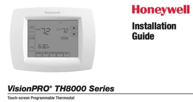
This Honeywell VisionPRO TH8000 Series Installation Manual is the 12-page guide for the touch-screen TH8321U1097, the only model listed on page 1. It covers wiring for conventional, heat pump, and IAQ systems, plus 70+ installer setup functions and system tests. The document is form 69-2389-03, © 2011 Honeywell International Inc.
Table of Contents
What the Manual Covers
Page 1 lists one model: “TH8321U1097: For up to 3 Heat/2 Cool heat pump or up to 2 Heat/2 Cool conventional systems with dehumidification, humidification, or ventilation”. To find your model number, “(Pull thermostat from wallplate and turn over to find model number)”. This VisionPRO TH8000 wiring guide covers the TH8321U installation for touch-screen programmable control.
The manual opens with three notices: a perchlorate warning for the lithium battery, a mercury notice if replacing an old control, and an electrical hazard caution: “Can cause electrical shock or equipment damage. Disconnect power before beginning installation.” The guide states: “Must be installed by a trained, experienced technician”.
Before You Install
Page 2 covers wallplate installation. “Separate wallplate from thermostat.” Mount it with “Drill 3/16″ holes for drywall. Drill 7/32″ holes for plaster.” After wiring, “Push excess wire back into the wall opening. Plug wall opening with non-flammable insulation.”
Page 6 shows how to mount the thermostat: “Remove tab. Align pins on back of thermostat with slots in wallplate, then push gently until thermostat snaps into place.” Then set the date and time before entering installer setup.
TH8000 Series Terminal Designations
Page 3 defines terminals for conventional and heat pump systems. Both share R (system power), C (common), S1/S2 (optional outdoor sensor), and U1/U1 (optional IAQ device). These TH8000 Series terminal designations apply to all wiring configurations.
| Terminal | Function |
|---|---|
| R | System power. Connect to secondary side of system transformer. |
| C | Common wire from secondary side of transformer. |
| W | 1st stage heat relay. |
| W2 | 2nd stage heat relay. |
| Y | 1st stage compressor contactor. |
| Y2 | 2nd stage compressor contactor. |
| G | Fan relay. |
| S1/S2 | Optional outdoor/remote/discharge sensor. |
| U1/U1 | Optional IAQ device. |
| Terminal | Function |
|---|---|
| R | System power. |
| C | Common wire. |
| Y | 1st stage compressor contactor. |
| Y2 | 2nd stage compressor contactor. |
| E/Aux | Auxiliary/Emergency heat relay. |
| G | Fan relay. |
| L | Heat pump reset (powered continuously when System is set to Em Heat; system monitor when set to Heat, Cool or Off). |
| O/B | Changeover valve for heat pumps. |
| S1/S2 | Optional outdoor/remote/discharge sensor. |
| U1/U1 | Optional IAQ device. |
Wiring Diagrams for Conventional Systems
Page 4 shows six conventional configurations for VisionPRO TH8000 wiring. Each lists the terminals used and any notes.
| System | Terminals | Notes |
|---|---|---|
| 1H/1C (1 transformer) | R W Y G C S1/S2 U1/U1 | [1, 6] |
| Heat Only | R W C S1/S2 U1/U1 | [1] |
| Heat Only (Series 20) | R W Y C S1/S2 U1/U1 | R to Series 20 “R”, W to “B”, Y to “W” |
| 2H/2C (1 transformer) | R W W2 Y Y2 G C S1/S2 U1/U1 | [1, 6] |
| Heat Only With Fan | R W G C S1/S2 U1/U1 | [1, 6] |
| Cool Only | R Y G C S1/S2 U1/U1 | [1] |
Notes: “[1] Power supply. Provide disconnect means and overload protection as required.” “[2] Optional 24VAC common connection.” “[6] Only works with single transformer systems.”
Heat Pump Wiring Diagrams
Page 5 covers four heat pump configurations for VisionPRO TH8000 heat pump wiring systems.
| System | Terminals | Notes |
|---|---|---|
| 1H/1C Heat Pump (no aux) | R Y G C O/B S1/S2 U1/U1 | [1, 3] |
| 2H/1C Heat Pump (with aux) | R Y G C E/Aux L O/B S1/S2 U1/U1 | [1, 2, 3, 4, 5] |
| 2H/2C Heat Pump (no aux) | R Y Y2 G C O/B S1/S2 U1/U1 | [1, 2, 3] |
| 3H/2C Heat Pump (with aux) | R Y Y2 G C E/Aux L O/B S1/S2 U1/U1 | [1, 2, 3, 4, 5] |
Notes: “[3] O/B set to control as either O or B in installer setup.” “[4] If L terminal is used, 24VAC common (terminal C) must be connected.” “[5] Heat pump reset (powered continuously when thermostat is set to Em. Heat; system monitor when set to Heat, Cool, or Off).”
IAQ Wiring (Humidification, Dehumidification, Ventilation)
Page 5 also shows six IAQ device configurations, all using the U1/U1 terminals. These indoor air quality connections let you integrate humidifiers, dehumidifiers, and ventilators with the thermostat’s control logic.
| Device | Wiring | Notes |
|---|---|---|
| Steam humidifier | R to U1, U1 to humidifier | [7] |
| Bypass flow-through humidifier | R jumpered to U1, U1 to humidifier | [7] |
| Whole house dehumidifier | R to U1, U1 to dehumidifier | [7] |
| A/C with low-speed fan | R jumpered to U1, U1 to dehumidification terminal | [7, 8] |
| Whole house powered ventilator | R to U1, U1 to ventilator | [7] |
| Non-powered ventilator | R jumpered to U1, U1 to ventilator | [7] |
Notes: “[7] Terminals are normally open dry contacts.” “[8] Equipment must include dehumidification terminal for low-speed fan.”
Installer Setup Functions
Pages 7-10 list 70+ VisionPRO TH8000 installer setup functions (0120-0710). The most critical are:
| Function | Setting | Options |
|---|---|---|
| 0170 | System type | 1-12 (conventional, heat pump, multistage) |
| 0180 | Fan control (heating) | 0 Gas/Oil, 1 Electric furnace |
| 0190 | Changeover valve (O/B) | 0 Cooling, 1 Heating |
| 0220 | 1st stage compressor cycle rate | 3 CPH recommended (1, 2, 4, 5, 6) |
| 0240 | 1st stage heat cycle rate | 5 Gas/oil <90%, 1 Steam, 3 Hot water, 9 Electric |
| 0300 | Manual/Auto changeover | 0 Manual, 1 Auto |
| 0371 | IAQ device on U1/U1 | 0 None, 1 Humidification, 2 Dehumidification, 3 Ventilation |
| 0400 | Ventilation control | 0-4 (off, on, lockouts) |
| 0580 | Compressor protection | 5 minutes recommended (0-5) |
| 0600 | Heat temperature range stop | 90°F max (40-89°F) |
| 0610 | Cool temperature range stop | 50°F min (51-99°F) |
The full list includes date/time (0120-0160), schedule format (0160), energy saving (0165), heat pump type (0173), auxiliary heat (0200), fossil fuel kit (0210), 2nd/3rd stage cycle rates (0230, 0260), backlight (0280), auto changeover deadband (0310), temperature display (0320), daylight savings (0330), remote sensor (0340), dual fuel control (0345-0347), heat pump lockouts (0350-0360), humidification control (0372-0374), dehumidification (0379-0394), ventilation (0401-0432), filter reminders (0500-0520), UV lamp (0520), adaptive recovery (0530), program periods (0540), clock format (0640), extended fan timer (0650-0660), keypad lock (0670), temperature control (0680-0690), display offset (0700-0701), and reset (0710).
Each VisionPRO TH8000 installer setup function controls a specific aspect of system operation. The manual prints factory defaults in bold throughout pages 7-10, so you can see at a glance which settings need changing for your particular installation.
Installer System Test
Pages 10-11 describe seven system tests. Enter test mode by pressing the system button repeatedly until “Test” appears.
| Test | System | Status |
|---|---|---|
| 1 | Cooling | 0 Off, 1 Compressor/fan on, 2 2nd stage |
| 2 | Fan | 0 Off, 1 On |
| 3 | Heating | 0 Off, 1 1st stage, 2 2nd stage, 3 3rd stage |
| 4 | Emergency heating | 0 Off, 1 On |
| 5 | Humidifier | 0 Off, 1 On |
| 6 | Dehumidifier | 0 Off, 1 On |
| 7 | Ventilator | 0 Off, 1 On |
The manual warns: “CAUTION: EQUIPMENT DAMAGE HAZARD. Compressor protection is bypassed during testing. To prevent equipment damage, avoid cycling the compressor quickly.”
Pages 11-12 explain special functions. Auto Changeover (0300) requires heat/cool settings at least 2°F apart (5°F if dehumidification is on).
Remote Sensor (0340) can display outdoor temperature or use a remote indoor sensor. Adaptive Intelligent Recovery (0530) learns how long the system takes to reach setpoints. Compressor Protection (0580) forces a wait before restart.
Dehumidification (0380) on TH8321 models can lower temperature up to 3°F below the cool setting. Heat pump control (0350-0360) sets compressor and auxiliary lockout temperatures. Ventilation (0400-0432) can be locked out by outdoor temperature. Dehumidification Away Mode (0390-0394) controls humidity when the home is unoccupied.
TH8000 Series Specifications and Accessories
Page 12 lists TH8000 Series specifications:
- Temperature ranges: Heat 40° to 90°F (4.5° to 32°C), Cool 50° to 99°F (10° to 37°C)
- Operating ambient: 0° to 120°F (-18° to 48.9°C)
- Shipping: -30° to 150°F (-34° to 66°C)
- Humidity: 5% to 90% (non-condensing)
- Dimensions: 4-9/16 in. H x 6 in. W x 1-3/8 in. D (116 mm H x 152 mm W x 35 mm D)
| Terminal | Voltage (50/60Hz) | Running Current |
|---|---|---|
| W | 20-30 Vac / 750 mV DC | 0.02-1.0 A / 100 mA DC |
| W2 | 20-30 Vac | 0.02-0.6 A |
| Y | 20-30 Vac | 0.02-1.0 A |
| Y2 | 20-30 Vac | 0.02-0.6 A |
| E/Aux | 20-30 Vac | 0.02-1.0 A |
| O/B | 20-30 Vac | 0.02-0.6 A |
| L | 20-30 Vac | 0.02-0.6 A |
| U1/U1 | 20-30 Vac | 0.02-0.6 A |
Accessories include outdoor sensor C7089U1006, remote indoor sensor C7189U1005, discharge air sensor C7735A1000, ventilators ER200B2006/HR200B1005, fresh air damper EARD6, humidifiers HE265A1007/HM512W1005, and cover plate 32003796-001.
FAQ
How do I find the model number?
“(Pull thermostat from wallplate and turn over to find model number)”. Page 1 lists TH8321U1097 for this TH8321U installation.
What’s the difference between conventional and heat pump terminals?
Heat pump systems add E/Aux (auxiliary/emergency heat), L (heat pump reset/monitor), and O/B (changeover valve). Conventional systems use W/W2 for heat stages and Y/Y2 for cooling stages.
How do I wire an outdoor sensor?
Connect to S1/S2 terminals. In installer setup, set function 0340 to 1 (outdoor sensor display only), 2 (outdoor sensor for control with lockouts), or 4 (discharge air sensor for desert humidity control).
What does the L terminal do?
The L terminal provides “Heat pump reset (powered continuously when System is set to Em Heat; system monitor when set to Heat, Cool or Off).” The wiring notes make the common connection mandatory when this terminal is used.
How do I set up dehumidification?
Set function 0371 to 2 for dehumidification control. For TH8321 models, function 0380 can activate cooling to reduce humidity by up to 3°F below the cool setting. For whole-house dehumidification, wire to U1/U1 and set function 0379 to 3.
What’s the compressor protection setting?
Function 0580 defaults to 5 minutes. The manual states: “Forces the compressor to wait a few minutes before restarting, to prevent damage. During this time, the message ‘Wait’ is displayed.” Options are 0-5 minutes.