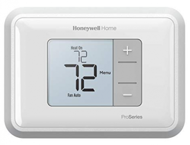
This page is for the Honeywell Home T3 Programmable Thermostat Installation Manual. The matching PDF on honeywellmanual.com is T3 Pro Thermostat Installation Instructions, document number 33-00520EFS-01 (M.S. 04-20, © 2020 Resideo Technologies, Inc.), a 36-page trilingual booklet with English on pages 1 to 12, French on pages 13 to 24, and Spanish on pages 25 to 36.
A note before you open the file: the “T3 Pro” line covers Honeywell Home’s non-programmable touchscreen thermostat, models TH3110U2008 and TH3210U2004. It has no weekly schedule; on the owner’s side you get a System mode selector, a Fan mode selector, and Installer Setup (ISU) for the technician. If the box says a programmable Honeywell Home model in the T5, T6, T9, or Wi-Fi 9000 family, this is the wrong document, and the model number printed behind the wallplate is the number to search instead.
Download T3 Pro Thermostat Installation Manual (PDF)
Contents
- What Is in the Box
- Safety and Power Before You Start
- Mounting the Thermostat
- Wiring: Terminals, Slider Tabs, and Diagrams
- System Modes and Fan Modes
- Installer Setup (ISU) Reference
- Specifications and Electrical Ratings
- Troubleshooting
- Getting Help and Warranty
What Is in the Box
Page 1 lists the package contents directly. The T3 Pro box contains the thermostat itself, a UWP™ Mounting System, a small decorative cover plate sized 4.72″ H x 5.9″ W (120 mm x 150 mm), mounting screws and drywall anchors, two AA batteries, and the thermostat literature set (this Installation Instructions plus a user insert). If any item is missing, stop before drilling and check with the seller, because the UWP door and the R/Rc slider tab are both integral to the wiring steps.
Safety and Power Before You Start
Three cautions are printed on page 11 and govern the whole install. Quote them as written:
CAUTION: ELECTRICAL HAZARD. Can cause electrical shock or equipment damage. Disconnect power before beginning installation.
CAUTION: EQUIPMENT DAMAGE HAZARD. Compressor protection is bypassed during testing. To prevent equipment damage, avoid cycling the compressor quickly.
CAUTION: MERCURY NOTICE. If this product is replacing a control that contains mercury in a sealed tube, do not place the old control in the trash. Contact your local waste management authority for instructions regarding recycling and proper disposal.
Both mounting pages open with the same operational rule: “Before starting, turn the power off at the breaker box or switch.” Do not rely on the wall switch alone when the air handler or furnace has a separate service switch.
Mounting the Thermostat
There are two mounting routes on pages 1 and 2, and you pick one depending on whether the old thermostat left marks on the drywall.
Optional cover plate installation. Use the cover plate when you need to hide paint gaps from the old thermostat. Mount the plate to the wall with any of its six screw holes, keeping it level and tightening without overtightening. Then hang the UWP on the top hook of the cover plate and snap its bottom into place. If there are no existing wall anchors, mark new holes and drill: 7/32″ (5.6 mm) for the red anchors and 3/16″ (4.8 mm) for the yellow anchors. The supplied screws pair by anchor color, #8 1-1/2″ (38 mm) with red and #6 1-1/2″ (38 mm) with yellow.
UWP Mounting System installation. Position the UWP on the wall, level it, mark both screw holes, and drill to the same 7/32″ or 3/16″ diameter depending on the anchor color. Pull open the UWP door and thread the wires through the wiring hole, then set the UWP over the anchors and tighten until the plate stops moving. Do not overtighten; close the door.
Final mounting on page 5: push excess wire back into the wall opening, close the UWP door so it sits flat without bulging, align the UWP with the back of the thermostat, and press gently until it snaps home. Then restore power at the breaker or switch.
Wiring: Terminals, Slider Tabs, and Diagrams
Power for the T3 Pro comes two ways at once. The UWP accepts a 24 VAC connection on R and C for primary power; the manual notes that C is optional if batteries are installed but is recommended. The two AA cells in the back cover primary or backup power. Wires release by pressing the terminal tab; never pull on the wire itself.
Page 3 lists every UWP terminal and what it does on a T3 Pro. Several are physically present but marked “Not used for T3 thermostat,” which is a common confusion when the old base has wires on them.
| Terminal | Function on a T3 Pro |
|---|---|
| R | 24 VAC power from the heating transformer (shareable via slider tab) |
| Rc | 24 VAC power from the cooling transformer (shareable via slider tab) |
| C | 24 VAC common; for two-transformer systems, from the cooling transformer |
| W | Heat (stage 1) on conventional systems. Do not use on heat pump applications |
| Y | Compressor contactor, stage 1 |
| G | Fan relay |
| O/B | Heat-pump changeover valve (configured in ISU 218) |
| AUX / W2 | Auxiliary heat (TH3210U only) |
| E | Emergency heat (TH3210U only) |
| S, L/A, A, Y2, U, K | Not used for T3 Pro wiring (slider tabs on U terminals should stay in place) |
The R/Rc slider tab. The UWP ships with a built-in jumper between R and Rc. If there is only one R wire, no matter whether it was landed on R, Rc, or Rh at the old thermostat, leave the slider in the up (one-wire) position. If one wire runs to R and a second to Rc, move the slider to the down (two-wire) position. The T3 Pro is a single-stage model, so the U-terminal slider tabs stay in place.
Pages 4 through 5 print wiring diagrams for eleven configurations. Conventional systems covered are 1H/1C with one transformer, 1H/1C with two transformers, heat-only, heat-only with fan, heat-only Series 20, heat-only power-open zone valve, and cool-only. Heat-pump systems covered are 1H/1C and 2H/1C with auxiliary heat (TH3210U only). Wire spec printed on page 4 is 18- to 22-gauge thermostat wire; shielded cable is not required.
System Modes and Fan Modes
Page 5 covers both selectors. Press Menu, then press the Mode (+) button to step through the available System modes, then press Done to lock one in. The manual lists these System modes: Auto, Heat, Cool, Em Heat (TH3210U only, on heat pumps with auxiliary heat, which locks out the compressor), and Off. It also notes that Heat On or Cool On may flash for five minutes because of compressor protection.
Press Menu, then the Fan (-) button to step through Fan modes. Auto runs the blower only when heating or cooling is active. On runs the blower continuously. If System is Off, the fan will still run when Fan is set to On.
Installer Setup (ISU) Reference
The T3 Pro enters ISU automatically the first time it is powered up after installation, and the manual tells the installer how to reach it later: hold the Menu button for about five seconds from the home screen. Inside ISU, press Edit (-) to change the value at the current step, press Next (+) to advance to the next setup number, and press Done to save and exit to the home screen. Every setup number is printed on pages 6 through 9. The table below collects the ones installers reference most; the numbers and defaults in bold match what the manual itself shows.
| ISU number | Purpose | Options and notes |
|---|---|---|
| 125 | Temperature Indication Scale | 0 = Fahrenheit, 1 = Celsius |
| 200 | Heating System Type | 1 = Conventional forced-air heat, 2 = Heat pump, 3 = Radiant heat, 5 = None (Cool only); default varies by model |
| 205 | Heating Equipment Type (shown when 200 is Conventional or Radiant) | Forced air: 1 = Standard-efficiency gas, 2 = High-efficiency gas, 3 = Oil, 4 = Electric, 5 = Hot-water fan coil. Radiant: 9 = Hot-water radiant, 12 = Steam |
| 218 | Reversing valve O/B (heat pump only) | 0 = O (energized in Cool), 1 = B (energized in Heat) |
| 220 | Cool stages / Compressor stages | 0 or 1 (set to 0 if there is no compressor or cooling stage) |
| 221 | Heat stages / Backup heat stages | Heat fixed at 1; Backup heat 0 or 1 |
| 230 | Fan control in Heat (shown when 205 is Electric forced air or Fan coil) | 1 = Equipment controls fan, 2 = Thermostat controls fan |
| 300 | System changeover | 0 = Manual, 1 = Automatic (turns the Auto System mode on the home screen) |
| 303 | Auto changeover differential | 0 to 5 °F (0 to 2.5 °C). The manual distinguishes this from deadband, which is fixed by firmware and not adjustable |
| 340 | Backup heat droop (TH3210U only) | 0 = Comfort, or a set droop from 2 °F up to 15 °F |
| 350 | Upstage timer to backup heat (TH3210U only) | 0 = Off, 1 = 30 min, 2 = 45 min, 3 = 60 min, and so on up to 5 hours |
| 365 | Compressor cycle rate, stage 1 | 1 to 6 cycles per hour, shown only when Cool / Compressor Stage is set to 1 |
| 370 | Heating cycle rate, stage 1 | 1 to 12 CPH. Defaults the manual lists by equipment: standard gas 5, high-efficiency gas 3, oil 5, electric 9, fan coil 3, hot-water radiant 3, steam 1 |
| 375 | Heating cycle rate, auxiliary heat (TH3210U only) | 1 to 12 CPH |
| 387 | Compressor protection | 0 = Off, 1 to 5 minutes. When a call arrives during the delay the screen shows “Wait” |
| 430 | Minimum Cool setpoint | 50 to 99 °F (10.0 to 37.0 °C); default 50 °F |
| 431 | Maximum Heat setpoint | 32 to 90 °F (0 to 32.0 °C); default 90 °F |
| 1400 | Backlighting | 0 = On demand, 1 = Continuous (requires a C-wire) |
| 1401 | Backlight brightness | 1 to 5, shown only when Continuous is selected |
| 1420 | Temperature display offset | -3 to +3 °F (-1.5 to +1.5 °C); 0 means the reading is unaltered |
The manual closes ISU with a plain sentence: “You have now finished installing and setting up your thermostat.” There is no owner-side reset procedure in this booklet; if a full ISU wipe is needed, that is an installer task.
Specifications and Electrical Ratings
Page 10 lists the ratings that govern where the thermostat can be used.
| Specification | Value from the manual |
|---|---|
| Heat setpoint range | 32 °F to 90 °F (0 to 32.0 °C) |
| Cool setpoint range | 50 °F to 99 °F (10.0 to 37.0 °C) |
| Operating ambient temperature | 32 °F to 102 °F (0 to 38.9 °C) |
| Shipping temperature | -20 °F to 120 °F (-28.9 to 48.9 °C) |
| Operating relative humidity | 5% to 90%, non-condensing |
| Thermostat size (H x W x D) | 3.86″ x 5.36″ x 1.08″ (98 x 136 x 27.4 mm) |
| Decorative cover plate, small | 4.72″ x 5.9″ (120 x 150 mm) |
| Terminal voltage (50/60 Hz) | All outputs are rated 20 to 30 VAC |
| Running current, W / W2 (Aux) / Y | 0.02 to 1.0 A (W2 is TH3210U only) |
| Running current, E / G / O/B | 0.02 to 0.5 A |
| Wire gauge | 18 to 22 gauge, unshielded |
Troubleshooting
Page 10 carries the manual’s own short troubleshooting table. It is reproduced here with the exact fixes the manual gives; nothing is added.
| Problem | What the manual advises |
|---|---|
| Display is blank | Check the circuit breaker and reset if necessary. Make sure the power switch for the heating and cooling system is on. Make sure the furnace door is closed securely. Make sure two fresh AA alkaline batteries are correctly installed (page 2). |
| Heating or cooling system does not respond | Press the Mode button to set System to Heat (page 5) and make sure the desired temperature is set higher than the inside temperature. To test cooling, press Mode to set System to Cool and make sure the desired temperature is set lower than the inside temperature. Check the circuit breaker and reset if necessary. Make sure the power switch at the heating and cooling system is on. Make sure the furnace door is closed securely. Wait five minutes for the system to respond. |
| “Cool On” or “Heat On” is flashing | The compressor protection feature is engaged. Wait five minutes for the system to restart safely, without damage to the compressor. |
| Aux heat runs during cooling | For heat pump systems, verify there is no wire attached to W on the UWP. See “Wiring heat pump systems” on page 4. |
| Cool runs on a call for heat | For heat pump systems, verify there is no wire attached to W on the UWP. See “Wiring heat pump systems” on page 4. |
Getting Help and Warranty
Page 11 directs support questions to customer.resideo.com or Honeywell Customer Care at 1-800-468-1502, and the same page shows how to pull the thermostat off the UWP for a service call. The footer on page 12 lists the Resideo mailing address, 1985 Douglas Drive North, Golden Valley, MN 55422, and identifies the document as 33-00520EFS-01, marking revision M.S. 04-20, © 2020 Resideo Technologies, Inc. The Honeywell Home trademark is used under license from Honeywell International, Inc.; the product itself is manufactured by Resideo Technologies, Inc. and its affiliates.
Because this document is a T3 Pro installation booklet, it does not carry a homeowner-side warranty statement. For warranty terms on a specific T3 Pro unit, check the printed card that shipped in the box or contact Honeywell Customer Care with the model number (TH3110U2008 or TH3210U2004) from the back of the thermostat.