Category Archives: Thermostat

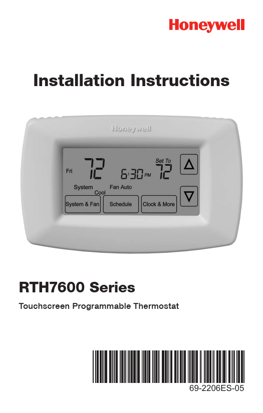
Honeywell RTH7600 Series Installation Instructions

Honeywell Touchscreen Programmable Thermostat RTH7600 Series Installation Instructions

The Honeywell Touchscreen Programmable Thermostat RTH7600 Series Installation Instructions walk through eleven numbered steps, from shutting off power to matching the thermostat to your equipment. This page follows that document, 69-2206ES—05, which is linked below. It covers mounting, wiring for conventional and heat pump systems, the function settings the installer menu exposes, and the eight faults the manual itself lists. Schedule programming is not part of this booklet; the only reference to the Operating Manual is on the setup page for Smart Response Technology.

Download the Honeywell RTH7600 Series Installation Instructions (PDF)

Download the official Honeywell RTH7600 Series Installation Instructions (PDF)

Table of Contents

What These Installation Instructions Cover

The booklet is an installer document, not a homeowner guide. Its own contents page divides the work into two halves. The first half is the eleven numbered steps on pages 1 to 11. The second half is called Advanced Installation and runs from page 13 to page 26.

Advanced Installation breaks down like this:

  • Thermostat setup, pages 13 to 20. Entering setup options, the date, system type, changeover mode, temperature format, daylight saving time, the filter reminder, Smart Response Technology, and the clock format.
  • Wiring, pages 21 to 23. Alternate wiring for conventional systems on page 21, the heat pump connection procedure on page 22, and alternate wiring for heat pumps on page 23. The two alternate charts are for old thermostats whose terminal letters do not match the new one.
  • Troubleshooting, pages 24 and 25. Eight symptom-and-action entries.
  • Customer assistance, page 26.

Page numbers on this page are the ones printed on the sheet. The English section of the PDF file begins on file page 3, so printed page 13 is file page 15.

The booklet’s introduction page states the two principles behind the sequence: the thermostat “works with virtually all System Types” and “is preset for the most common system.”

Compatibility and Power Requirements

One sentence on page 11 decides whether the RTH7600 Series belongs on your wall at all. The thermostat “works on 24 volt or 750 mV systems. It will NOT work on 120/240 Volt systems.”

Page 11 also splits the work by system type, and the split is the reason some installations stop at step 11 while others continue into the advanced pages:

  • Single Stage Heat and Cool. The manual’s response is “Congratulations, you’re done!”
  • Multistage Heat and Cool, heat pump without backup heat, heat pump with backup heat, heat only, or cool only. These continue into the advanced pages, which the booklet describes as the step that matches the thermostat to the system type.

The same page defines a heat pump for readers who are unsure: “an air conditioner that provides cooling in the summer, and also runs in reverse in the winter to provide heating.” If the system type is still unclear, the manual directs the reader to the toll-free line at 1-800-468-1502.

What the terminal strip accepts

The conventional strip carries eight positions: R, RC, W, Y, G, C, W2 and Y2. The heat pump strip carries nine: R, RC, O/B, Y, G, C, L, E and Aux. The extra positions on each side are what separate a single-stage installation from a multistage one, and the function table later in this page is where those positions get declared.

Parts the Manual Names

The booklet references only what the installation actually touches:

  • Mounting screws and anchors, described in step 5 as “the included screws and anchors.”
  • Wire labels, described in step 3 as “the supplied wire labels.”
  • Two AA alkaline batteries, installed in step 7, which also has you remove a tab.
  • A small piece of wire, called for on the heat pump pages when the E and Aux terminals do not each have a conductor connected.

A screwdriver is required by the heat pump wiring steps, which say to “loosen screws, insert wires into hole, then tighten screws.” Two drill bits appear in step 5: 3/16-in. for drywall and 3/32-in. for plaster.

Step-by-Step Installation (Steps 1 to 11)

The eleven steps in the booklet run in one direction, with one branch at the end. Steps 1 to 9 are physical work at the wall. Steps 10 and 11 are done on the screen with the power back on.

Step 1: Turn off power to the heating and cooling system

The first page is a single instruction and a note. The instruction is to cut power to the heating and cooling system. The note is for readers who have already worked through the Quick Start Guide and only need to match the thermostat to a system type: that reader is sent straight to page 13.

Step 2: Remove the old thermostat

The old thermostat comes off, but its wallplate stays on the wall with the wires still attached. The page carries a warning about the old unit: if it holds a sealed tube containing mercury, the back cover of the booklet gives the disposal instructions.

Step 3: Label the wires with the supplied tags

Each conductor gets a tag as it is disconnected. The page adds one caution that matters more than it looks: “Wire color may not match labels.” Colour is not the identifier here. The tag is.

Step 4: Separate the wallplate from the new thermostat

The new wallplate arrives fitted to the back of the thermostat body and has to come off before it can be mounted. Step 4 is that separation and nothing else.

Step 5: Mount the new wallplate

The wallplate goes on with the included screws and anchors. The booklet prints two pilot-hole sizes on the same page:

  • 3/16-in. holes for drywall.
  • 3/32-in. holes for plaster.

Step 6: Connect the wires

The entire instruction is four words: “Simply match wire labels.” Each tag goes to the terminal of the same letter, and the wires are inserted into the holes and the screws tightened.

One exception sits under the drawing. Remove the metal jumper between R and Rc if both terminals will carry a wire. The full jumper rules are on page 21 and are covered under Wiring below.

Two routing notes appear on the page. A heat pump system sends the reader to pages 22 and 23. Terminal letters on the old thermostat that do not match send the reader to page 21.

Step 7: Install the batteries

Two AA alkaline batteries go into the back of the thermostat, and a tab is removed. The drawing labels the two locations as “Back of thermostat” and “Remove tab.”

Step 8: Install the thermostat onto the wallplate

The body pushes onto the mounted wallplate. Step 8 is that single action.

Step 9: Turn the power back on

Power returns to the heating and cooling system. Everything after this point happens on the screen.

Step 10: Set the time and date

The screen presents four values in a fixed order, with the arrow buttons changing the value and the NEXT button moving to the next one:

  1. Press the up or down arrow to set the month, then press NEXT.
  2. Press the arrow buttons to set the day, then press NEXT.
  3. Press the arrow buttons to set the year, then press DONE.
  4. Press the arrow buttons to set the time, then press DONE to save and exit.

Step 11: Match the thermostat to your system type

This step is a branch, not a task. A single-stage heat and cool system finishes here. Every other system type continues into Advanced Installation, where function 0170 declares what the thermostat is connected to.

If the date and time were already set on page 10, the advanced section notes that the reader can press NEXT through to function 0170 and go directly to the system type setting.

Wiring: Conventional and Heat Pump Terminals

Two drawings cover the terminals, one for each system family. In both cases the rule is the same as step 6: the tag on the wire and the letter on the terminal have to match.

Conventional terminal strip

Terminal Function
R Power side
RC Power side, jumpered to R by the metal jumper
W Heat
Y Cool
G Fan
C Common
Y2 Second cooling stage
W2 Second heating stage

The letters in the left column are printed on the thermostat. The function words beside them are added here to make the strip readable; the booklet prints the letters only.

Heat pump terminal strip

Terminal Function
R Power side
RC Power side, jumpered to R
O/B Changeover valve
Y Compressor
G Fan
C Common
L Service indicator
E Emergency heat
Aux Auxiliary heat

The same note applies to this table: the letters are the manual’s, the function words are added here. The heat pump page adds a fourth wiring step beyond matching, inserting and tightening: if E and Aux do not each have a wire connected, a small piece of wire joins them to each other. A fifth note says to push any excess wire back into the wall opening.

Alternate wiring when the old letters do not match

Older thermostats carry lettering this one does not. Page 21 has the conventional chart and page 23 has the heat pump chart. Both are read the same way: find the old label on the right, land the wire on the terminal at the left.

Conventional systems, page 21:

Old thermostat label Terminal on the RTH7600
Rc or R Rc
R, RH, 4, or V R
W, W1, or H W
Y, Y1, or M Y
G or F G
C, C1, X, or B C
Y2 Y2
W2 W2

Heat pump systems, page 23:

Old thermostat label Terminal on the RTH7600
Rc or R Rc
R, V, or VR R
O, H, or B O/B
Y, Y1, or M Y
G or F G
C, X, or B C
L or F L
E, X, or X2 E
Aux, W, W1, or W2 Aux

The R and Rc jumper

A metal jumper connects R and Rc on the terminal strip, and step 6 says to remove it if both terminals will carry a wire. Page 21 gives the three cases in full:

  • Both R and Rc wires present. Remove the metal jumper and connect both.
  • Old thermostat had R and RH wires. Remove the metal jumper, connect the R wire to the Rc terminal, and connect the RH wire to the R terminal.
  • No second power wire. Leave the jumper in place.

On a heat pump the instruction reverses: page 23 says to leave the metal jumper in place, connecting R and Rc.

Where the manual stops and calls a contractor

Three conditions on page 23 end the installation. Each one is a stop, not a caution:

  • An old thermostat with both V and VR wires.
  • An old thermostat with Y1, W1 and W2 wires.
  • Separate O and B wires, when another wire already occupies the C terminal. The manual’s instruction for the O and B case is to attach the B wire to the C terminal, and to stop only if C is already taken.

One further rule ties two terminals together: if the L terminal is used, the C terminal must have a wire, and the manual directs the reader to a contractor when there is no C wire.

Advanced Installation: Function Settings

Everything from page 13 onward is reached through the setup menu. The menu holds fifteen functions, numbered in hundreds, and the numbers are printed on the screen rather than in the booklet’s headings.

How to open the setup menu

  1. Press and release the left button.
  2. Press and hold the center button until the screen changes, which the manual puts at approximately five seconds.

Inside the menu, the arrow buttons change the value that is showing, NEXT moves to the next function number, and DONE saves and exits. The booklet notes that some functions may not appear at all, depending on selections already made. That is why a single-stage installation sees a shorter menu than a heat pump.

Function table

Function What it sets Options
0120 Year, first two digits 20 = year 20xx · 21 = year 21xx
0130 Year, last two digits 01 to 99
0140 Month 01 to 12
0150 Date 01 to 31
0170 System type 1 = heat and cool, gas, oil or electric with central air · 2 = heat pump without backup or auxiliary heat · 3 = heat only · 4 = heat only with fan · 5 = hot water heat only, no fan · 6 = cool only · 7 = heat pump with backup or auxiliary heat · 8 = two heat stages on W and W2, two cooling stages on Y and Y2 · 9 = two heat stages on W and W2, one cooling stage on Y · 10 = one heat stage on W, two cooling stages on Y and Y2
0180 Heating fan control 0 = gas or oil heat, system controls fan operation · 1 = electric heat, thermostat controls fan operation
0190 Heat pump changeover valve 0 = cooling changeover valve, for an O wire on O/B · 1 = heating changeover valve, for a B wire on O/B
0240 Heating cycle rate 5 = gas or oil furnace under 90% efficiency · 9 = electric furnace · 3 = hot water system or gas furnace over 90% efficiency · 1 = gas or oil steam or gravity system
0270 Emergency heat cycle rate, heat pumps only 9 = electric furnace · 5 = gas or oil furnace under 90% efficiency · 3 = hot water system or gas furnace over 90% efficiency · 1 = gas or oil steam or gravity system
0300 Manual or auto changeover 0 = manual, Heat, Cool and Off · 1 = automatic, Heat, Cool, Auto and Off, which turns on heat or cool from room temperature and keeps a minimum 3°F difference between the heat and cool settings
0320 Temperature format 0 = Fahrenheit · 1 = Celsius
0330 Daylight saving time 0 = off, no adjustment · 1 = on, for areas that do not use the 2007 DST calendar · 2 = on, for areas that use the 2007 DST calendar
0500 Furnace filter change reminder 0 = off · 1 = 10-day run time, about 1 month · 2 = 30 days, about 3 months · 3 = 60 days, about 6 months · 4 = 90 days, about 9 months · 5 = 120 days, about 1 year · 6 = 365 days, about 3 years
0530 Smart Response Technology 1 = on · 0 = off
0640 Clock format 12 = 12-hour clock · 24 = 24-hour clock

The booklet defers one function to another document: function 0530 refers the reader to the Operating Manual for an explanation of Smart Response Technology. The setup pages end with DONE to save and exit.

Troubleshooting

The manual’s troubleshooting pages are a two-column list of eight entries, running across pages 24 and 25. Symptom wording and the action column below follow that list. The cause column is added here, because the manual prints actions without stating a cause.

Symptom Likely cause What the manual says to do
Display is blank The batteries are missing or not seated Make sure fresh AA alkaline batteries are properly installed (see page 7).
Cannot change system setting to Cool The system type does not include cooling Check Function 0170: System Type to make sure it is set to match your heating and cooling equipment (see page 16).
Fan does not turn on when heat is required The fan control setting does not match the heating equipment Check Function 0180: Heating Fan Control to make sure it is set to match your heating equipment (see page 17).
Heating system is running in cool mode The system type is declared incorrectly Check Function 0170: System Type to make sure it is set to match your heating and cooling equipment (see page 16).
Red light is on The thermostat is in Emergency Heat mode, or it is not and something else is wrong If thermostat is in Emergency Heat mode the red light is normal. It shows that the thermostat is in emergency heat mode. If thermostat is not in Emergency Heat mode, contact a qualified service contractor for repair.
Heating or cooling system does not respond The system switch position, the setpoint, or power at the equipment Press SYSTEM to set system to Heat. Make sure the temperature is set higher than the Inside temperature. Press SYSTEM to set system to Cool. Make sure the temperature is set lower than the Inside temperature. Check circuit breaker and reset if necessary. Make sure power switch at heating & cooling system is on. Make sure furnace door is closed securely. Wait 5 minutes for the system to respond.
“Wait” appears on the screen Compressor protection is holding the compressor back Compressor protection feature is engaged. Wait 5 minutes for the system to restart safely, without damage to the compressor.
Heat pump issues cool air in heat mode, or warm air in cool mode The changeover valve setting is inverted Check Function 0190: Heat Pump Changeover Valve to make sure it is properly configured for your system (see page 17).

Four of the eight entries route back to a function number, which is the pattern worth noticing: 0170 appears twice, 0180 once, and 0190 once. After mounting and wiring, most faults on this thermostat are settings that were left on the wrong value rather than failed parts.

Page 26 of the booklet gives the escalation path. Assistance is at http://yourhome.honeywell.com or on the toll-free line, 1-800-468-1502. The same number appears on the inside front cover, with the note to call before returning the thermostat to the store, and again on the step 6 page for wiring assistance.

Specifications

  • Model line: RTH7600 Series, touchscreen programmable thermostat.
  • Document: 69-2206ES—05, revision 04-11, printed in the U.S.A., © 2011 Honeywell International Inc.
  • Power source: two AA alkaline batteries, installed at step 7.
  • System voltage: 24 volt or 750 mV. Not for 120/240 volt systems.
  • Conventional terminals: R, RC, W, Y, G, C, Y2, W2.
  • Heat pump terminals: R, RC, O/B, Y, G, C, L, E, Aux.
  • System types: ten options at function 0170, covering single-stage heat and cool, heat pump with and without backup heat, heat only, hot water heat only, cool only, and three multistage combinations.
  • Changeover: manual or automatic, set at function 0300. Automatic mode keeps a minimum 3°F between the heat and cool settings.
  • Compressor protection: a five-minute wait is printed in the troubleshooting list and applies to the “Wait” message.
  • Filter reminder intervals: 10, 30, 60, 90, 120 or 365 days of run time, set at function 0500.
  • Warranty: one year from the date of purchase, excluding the battery.
  • Operating caution: to avoid possible compressor damage, do not run the air conditioner when the outside temperature drops below 50°F (10°C).

Frequently Asked Questions

Where can I get the RTH7600 Series installation instructions as a PDF?

The download link at the top and bottom of this page opens the manufacturer PDF for this document. It holds the eleven numbered steps, the terminal drawings for conventional and heat pump systems, the alternate wiring charts, and the fifteen-function setup table.

What batteries does the RTH7600 Series take?

Two AA alkaline batteries, installed in step 7 on the back of the thermostat, and the step also has you remove a tab. The troubleshooting list sends a blank display back to that same page.

Does the RTH7600 need a C wire?

There is a C position on the strip, and step 7 installs two AA alkaline batteries as the supply the booklet calls for. On a heat pump the C terminal matters in one case. If the L terminal is used, the manual says the C terminal must carry a wire. It sends you to a contractor when there is no C wire.

Why will the thermostat not switch to Cool?

Function 0170, System Type, is probably set to a type that has no cooling. The manual’s own answer is to check that function against your equipment. The same function is the manual’s answer when the heating system runs in cool mode.

What does a Wait message on the screen mean?

Compressor protection is engaged. The manual says to wait 5 minutes for the system to restart safely, without damage to the compressor. Nothing needs resetting.

How do I open the installer setup menu?

Press and release the left button, then press and hold the center button until the screen changes, which takes about five seconds. The arrows change a value, NEXT moves to the next function number, and DONE saves and exits.

Can the RTH7600 Series control a two-stage system?

Yes. The strip carries W2 and Y2, and function 0170 offers three multistage options: two heat stages with two cooling stages, two heat stages with one cooling stage, and one heat stage with two cooling stages. A single-stage heat and cool system is the one type that finishes at step 11.

When should I stop and call a contractor instead?

The heat pump wiring page names three stops. They are an old thermostat with both V and VR wires, one with Y1, W1 and W2 wires, and separate O and B wires where the C terminal is already occupied. Use of the L terminal without a C wire is a fourth case the same page sends to a contractor.
Honeywell 7 day programmable thermostat RTH7600D Operating Manual

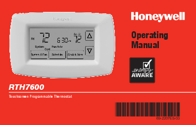
Honeywell 7 day programmable thermostat RTH7600D Operating Manual

This page is a plain walk-through of the Honeywell 7 day programmable thermostat RTH7600D Operating Manual (document 69-2207EF). The RTH7600D is Honeywell’s touchscreen 7-day model, so the steps here differ from the button-based thermostats you may have used before. Every point is taken from the official manual and labeled with its section so you can check it. The operating manual PDF is linked at the top; read it alongside your unit, especially before you touch any wiring.

Download the official Honeywell RTH7600D Operating Manual (PDF)

Table of Contents

What the RTH7600D Is

The RTH7600D is a touchscreen, 7-day programmable thermostat for a central heating and cooling system. Honeywell’s “About your new thermostat” section lists its core capabilities:

  • A large touchscreen display with a backlight, readable even in the dark.
  • Daily program schedules that balance comfort and energy savings.
  • One-touch temperature control that overrides the schedule at any time.
  • Precise control that holds the room within 1°F of the temperature you set.
  • A furnace filter change/check reminder.

It also offers Smart Response learning, Auto Changeover between heat and cool, and a compressor-protection delay. The unit is a 1-heat / 1-cool thermostat, so it is not meant for multistage systems.

The Controls and the Screen

The RTH7600D has a small set of physical buttons and on-screen softkeys (Quick reference to controls):

  • Arrow keys. Adjust the temperature or make selections from the on-screen menus.
  • CLOCK. Open the clock (time and day) setting, and the filter reminder.
  • SCHEDULE. Open the program schedule.
  • SYSTEM & FAN. Switch to the System or Fan menu, then press DONE to save or GO BACK to cancel.

The home screen shows the day, the time, the set temperature, and the current room temperature, plus the active System and Fan settings. Temporary messages include Cool On, Heat On, Recovery (Smart Response is working early) and Wait (compressor protection is delaying the restart).

First-Time Setup

After you mount the thermostat and restore power, Honeywell says it is essentially ready to run: it ships pre-programmed. The only required step is to set the time and day. The defaults it lists are:

  • Fan: Auto.
  • System: Heat.
  • Program: energy-saving levels assuming you wake at 6 AM, leave at 8 AM, return at 6 PM and sleep at 10 PM.

Adjust any of these to your own routine. The manual pre-set schedule is Wake 6:00 AM 70°, Leave 8:00 AM 62°, Return 6:00 PM 70° and Sleep 10:00 PM 62° for heating (with separate cooling setpoints).

Setting the Clock, Fan and System

  • Clock. Press CLOCK, then press the up or down arrow to set the time; press and hold an arrow to move faster. Press DONE to save (GO BACK exits without saving). The clock keeps date and time and updates for daylight saving on its own.
  • Fan. Press SYSTEM & FAN, then FAN, and choose On (fan runs continuously) or Auto (fan runs only during heating or cooling). Press DONE.
  • System. Press SYSTEM & FAN, then SYSTEM, and choose Heat, Cool or Auto. In Auto the thermostat decides whether to heat or cool to reach the setpoint. Press DONE.

Programming the Daily Schedule

You can set four periods each day (Wake, Leave, Return and Sleep) with different temperatures, and different settings for weekdays and weekends. Press SCHEDULE, then for each period set the time with the arrow keys, confirm, and set the temperature. The manual notes you can program the weekday schedule first, then the weekend days. Set the System to Heat or Cool first, because heating and cooling are programmed separately.

Around-the-program economy is the goal: lower the heat and raise the cooling while you are away or asleep, and bring them back for morning and evening.

Overriding the Schedule

For a quick change, press an arrow key. The screen shows Temporary, and the new temperature holds only until the next scheduled period, then the program resumes. To override all periods, use the Hold option; to clear the hold and return to the schedule, press Cancel (or RUN to resume, as the on-screen prompt shows).

Auto Changeover, Smart Response and Compressor Protection

  • Auto Changeover. With System set to Auto, the thermostat picks heating or cooling to reach the set temperature, so you rarely change modes by hand. Honeywell cautions against running cooling when the outdoor temperature is below 50°F (10°C).
  • Smart Response. The thermostat learns how long your system takes to reach a setpoint and starts early so the temperature is met on time; Recovery appears while it is running ahead of a period.
  • Compressor Protection. After a shutdown the thermostat waits a few minutes before restarting the compressor to avoid damage; Wait is shown during this delay.

In Case of Difficulty

This is the manual’s own troubleshooting guidance (In case of difficulty). For a heating or cooling system that does not respond, it lists these checks:

  • Press SYSTEM and set it to Heat, then make sure the set temperature is higher than the indoor temperature; or set it to Cool with the temperature lower than indoor.
  • Check the circuit breaker and reset it if needed.
  • Make sure the power switch at the heating and cooling system is on.
  • Make sure the furnace door is closed securely.
  • If Wait is shown, the compressor protection timer is active; wait about 5 minutes for the system to restart.

Batteries and Wiring

The RTH7600D runs on two fresh AA alkaline batteries. If your thermostat was wired to run on AC power, batteries are optional and act as backup. Install fresh batteries as soon as LO BATT starts flashing; the warning appears about 30 days before the batteries die, and Honeywell recommends changing them once a year or before a trip longer than a month. Note the disposal guidance: the unit contains a lithium battery that may contain perchlorate material.

This operating manual covers use, not installation. Wiring, terminal layout and system-type setup are in the separate RTH7600 Installation Instructions (69-2206), which Honeywell ships with the thermostat; follow that document and switch off power before touching any wire.

Specifications

  • Type: 7-day programmable, touchscreen, 1 heat / 1 cool.
  • Display: Large touchscreen with backlight.
  • Program: Four periods per day (Wake, Leave, Return, Sleep); weekday and weekend settings.
  • Temperature control: Holds within 1°F of the setpoint.
  • System modes: Heat, Cool, Auto.
  • Fan modes: On, Auto.
  • Power: Two AA alkaline batteries (backup if wired for AC power).
  • Extras: Smart Response, Auto Changeover, compressor protection, filter reminder.
  • Warranty: 1-year limited (excludes battery); Honeywell Customer Care 1-800-468-1502.
  • Not for: Multistage systems.

FAQ

Is the RTH7600D a 7-day programmable thermostat?

Yes. It is a 7-day programmable model with four time periods a day (Wake, Leave, Return, Sleep) and separate weekday and weekend settings.

How do I set the clock and day?

Press CLOCK, use the up or down arrow to set the time, then set the day, and press DONE. The clock holds date and time and adjusts for daylight saving on its own.

Why does the screen show “Wait”?

That is compressor protection. The thermostat delays the compressor by a few minutes after a shutdown to prevent damage, then starts normally.

What batteries does the RTH7600D use?

Two fresh AA alkaline batteries. If the unit is wired for AC power, the batteries serve as backup. Replace them when LO BATT flashes.

What is the “Recovery” message?

Recovery means Smart Response is running the system ahead of a scheduled period so the temperature is met at the time you set.

Where do I find wiring for this thermostat?

The operating manual does not include wiring. See the separate RTH7600 Installation Instructions (69-2206) that ships with the unit, and always switch off power before handling wires.


Honeywell Digital Thermostat T6811DP08 Instruction Manual

Honeywell Digital Thermostat T6811DP08 Instruction Manual

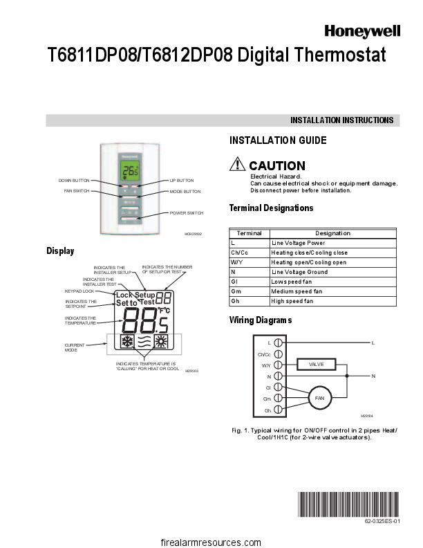
The Honeywell Digital Thermostat T6811DP08 User Manual helps technicians install, wire, configure and troubleshoot this non-programmable thermostat for two-pipe fan coil systems. This guide covers the installation document, terminal designations, operating controls, installer settings, test procedures and common faults. It also explains the electrical safety precautions required before working on this 110 VAC thermostat.

Quick Facts and Specifications

The T6811DP08 is a digital fan coil thermostat designed for manual heating and cooling selection, ventilation and three-speed fan control. It is relevant to building maintenance teams working with fan coil units in hotels, apartments, offices and similar facilities.

Specification

T6811DP08 Details

Model

Honeywell T6811DP08

Supply voltage

110 (+20%, −10%) VAC

Supply frequency

50/60 Hz

System application

Two-pipe fan coil

Control modes

Heat, Cool and Vent

System selection

Manual heating/cooling changeover

Fan control

Three speeds: Low, Medium and High

Temperature setting range

10–32°C

Temperature control accuracy

±1°C at 21°C

Electrical load rating

4(2) A

Protection rating

IP20

Operating temperature

−18 to 49°C

Installation

Wall-mounted

Mounting boxes

86 × 86 mm or 2 × 4 inch junction box

Programming

Non-programmable; no seven-day schedule

Important: The T6811DP08 is a line voltage thermostat, not a conventional 24 VAC low-voltage thermostat. Do not assume that wiring instructions for other Honeywell models apply to this unit.

Where to Download the Official Manual PDF

The principal installation document for this thermostat family is identified as 62-0325ES-01. It covers the T6811DP08 and T6812DP08 models.

Installation Instructions: 62-0325ES-01

This document is the primary reference for installation and servicing. It includes display indicators, terminal designations, wiring diagrams for two-wire and three-wire valve actuators, wall mounting, Installer Setup, Installer Test, normal operation and troubleshooting.

View the T6811DP08/T6812DP08 Installation Instructions PDF. This is an archived copy of a Honeywell-branded document, rather than a verified current manufacturer-hosted download.

Understanding the Display

Indicator

Meaning

Temperature

Displays room temperature or the value selected by the display configuration.

Setpoint

Identifies the selected temperature setting.

Current Mode

Shows the active mode: Heat, Cool or Vent.

Heating or Cooling Demand

Indicates that the thermostat is calling for heating or cooling.

Keypad Lock

Indicates that keypad lockout is active.

Setup

Indicates Installer Setup mode.

Test

Indicates Installer Test mode.

Setup/Test Number

Identifies the configuration item or test function displayed.

The display's appearance can vary according to the active mode and installer configuration.

Button and Switch Functions

  • UP: In normal Heat or Cool operation, increases the selected temperature setpoint. It also changes values in Installer Setup and Installer Test modes.
  • DOWN: Decreases the temperature setpoint or changes the value of the selected configuration item.
  • MODE: Cycles through Heat, Cool and Vent.
  • POWER switch: Turns the thermostat on or off.
  • FAN switch: Selects Low, Medium or High fan speed.

In Vent mode, the fan operates without a heating or cooling demand from the thermostat. If a button appears unresponsive, check whether the thermostat is switched off, keypad lockout is active or Vent mode has been selected.

Terminal Designations and Wiring Diagram

Correct terminal identification is essential when installing or replacing a Honeywell T6811DP08.

Terminal

Function

Application

L

Line voltage power

Incoming live supply

Ch/Cc

Heating close / Cooling close

Valve actuator control

W/Y

Heating open / Cooling open

Valve actuator control

N

Neutral supply connection

Electrical supply common

Gl

Low-speed fan

Fan motor low-speed input

Gm

Medium-speed fan

Fan motor medium-speed input

Gh

High-speed fan

Fan motor high-speed input

Wiring terminology: The original document's extracted terminal table describes N as a line-voltage ground connection. Do not interpret this as permission to connect neutral and protective earth together. Confirm the actual supply and protective-earth requirements against applicable electrical regulations and verified manufacturer documentation before wiring.

Two-Wire Valve Actuator

The installation document includes a typical ON/OFF control arrangement for a two-pipe heating/cooling system with a two-wire valve actuator. The actuator wiring arrangement depends on its electrical design. Follow the manufacturer's diagram to identify the correct actuator connections and the terminals used for opening and closing. Do not infer a complete actuator circuit from terminal names alone.

Three-Wire Valve Actuator

The manual also illustrates a typical arrangement for a three-wire valve actuator. A three-wire actuator may use different connections for its control functions than a two-wire ON/OFF actuator. The exact connections depend on the actuator design and must match the wiring diagram supplied for that device.

Before connecting the valve, establish:

  • Whether the actuator is designed for the available supply voltage.
  • Which conductors provide the required control functions.
  • Which thermostat terminals the verified diagram specifies.
  • Whether the existing system is configured for heating or cooling.

Do not interchange two-wire and three-wire actuator wiring arrangements without confirming compatibility.

DANGER: 110 VAC LINE VOLTAGE — ELECTRIC SHOCK HAZARD

The T6811DP08 operates from a 110 VAC nominal supply. Contact with live conductors can cause serious injury or death.

  • Disconnect the electrical supply before installation, wiring, inspection or maintenance.
  • Verify that the circuit is de-energised using an appropriate test instrument.
  • Do not treat this thermostat as a 24 VAC low-voltage device.
  • Have installation and electrical troubleshooting performed by a qualified electrician or HVAC technician.
  • Restore power only after all connections, covers and mounting screws have been checked.

Wiring Diagram Reference

Consult the wiring diagrams in document 62-0325ES-01 for the illustrated two-wire and three-wire actuator arrangements. Never use a generic fan coil wiring diagram as a substitute for the correct diagram for the installed valve, fan motor and supply arrangement.

Installation Steps

Step 1: Mount the Back Cover

Isolate the electrical supply. Pull the existing conductors through the wiring opening and position the back cover over the wall junction box. The thermostat is intended for installation on an 86 × 86 mm or 2 × 4 inch junction box, subject to confirmation of the actual mounting arrangement.

Step 2: Secure the Back Cover

Insert the mounting screws and tighten them securely. Check that the back cover sits correctly against the mounting surface without pinching or damaging conductors.

Step 3: Connect the Wires

Loosen the relevant screw terminals. Insert each conductor into its designated terminal and tighten the terminal screw. Verify every connection against the correct wiring diagram before proceeding.

Step 4: Fit the Thermostat Body

Align the top of the thermostat with the back cover. Push the body down into position as shown in the installation instructions. Check that the housing is properly seated.

Step 5: Tighten the Locking Screw

Insert the locking screw into the hole at the bottom of the thermostat and tighten it. Before restoring power, check the wiring, enclosure, terminal tightness and mechanical fit.

After installation, confirm normal display operation, fan-speed selection, mode selection and heating or cooling response.

Installer Setup Menu Walkthrough

Installer Setup changes how the thermostat operates. Incorrect settings can prevent the device from controlling the intended HVAC system correctly.

Entering Installer Setup

  1. Ensure the thermostat is powered and accessible.
  2. Press and hold UP and MODE simultaneously for three seconds.
  3. Confirm that the display indicates Installer Setup.
  4. Press UP or DOWN to change the selected setting.
  5. Press MODE to advance to the next function.
  6. Press and hold UP and MODE simultaneously for three seconds to exit and save the settings.

Record the original settings before making changes, particularly in occupied buildings where the thermostat is part of a larger maintenance system.

Installer Setup Number Reference Table

The following reference is based on the settings listed in document 62-0325ES-01. Verify the values against a legible original copy before relying on them for commissioning.

Number

Name

Available Values

Default

1

System Type

0: Heat only; 1: Cool only; 2: Two-pipe, manual heating/cooling

2

9

Temperature Scale

°F or °C; verify displayed option coding against the original table

°C

13

CPH Value for Heat

1–12

4

14

CPH Value for Cool

1–6

3

18

Display Temperature Adjustment

−2, −1.5, −1, −0.5, 0, +0.5, +1, +1.5, +2°C, with corresponding Fahrenheit values

0°C

19

Temperature Display Mode

0: Room temperature; 1: Setpoint

0

20

Heating Range Stops

10–32°C; 50–90°F

32°C / 90°F

21

Cooling Range Stops

10–32°C; 50–90°F

10°C / 50°F

22

Keypad Lockout

0: All keys available; 1: All keys locked out

0

  • System Type 1 selects a cooling-only configuration; System Type 0 selects heating-only.
  • System Type 2 is the listed default for two-pipe manual heating/cooling operation.
  • CPH means cycles per hour. Change these parameters only when the application and manufacturer guidance justify doing so.
  • Setting 18 adjusts the displayed temperature offset. It should not be used to conceal an actual HVAC control or sensor fault.
  • Settings 20 and 21 establish heating and cooling setpoint limits.
  • Setting 22 controls keypad lockout.

The original table's temperature-scale option coding should be checked against a legible copy of the relevant document before reproducing it as an exact menu-value sequence: [VERIFY].

Installer Test Mode

Installer Test mode helps a qualified technician check heating and cooling outputs independently of normal user operation.

Entering Installer Test

  1. Press and hold UP and DOWN simultaneously for three seconds.
  2. Confirm that Installer Test mode is displayed.
  3. Use UP or DOWN to change the selected test value.
  4. Press MODE to advance to the next test function.
  5. Exit by pressing and holding UP and MODE simultaneously for three seconds.

Number

Function

Available Values

10

Heating Test

0: Heat Off; 1: Heat On

30

Cooling Test

0: Cool Off; 1: Cool On

70

Software Information

Press UP to view items 71–73

71

Software Version

Major version

72

Software Version

Minor version

73

Identification Code

Software identification value

Items 71–73 display information associated with the installed thermostat. Read the actual values from the device; do not assume them from another unit.

During output tests, verify the system's response and follow the site's electrical safety procedures. Do not force a valve or fan output if doing so could damage connected equipment.

Daily Operation

Switching the Thermostat On or Off

Use the physical POWER switch to turn the thermostat on or off. After switching it on, check the display and confirm that the selected mode matches the intended system operation.

Selecting Fan Speed

Move the FAN switch to the required setting:

  • Low: Low fan speed.
  • Medium: Medium fan speed.
  • High: High fan speed.

The selected speed determines the fan output used during operation.

Selecting Heat, Cool or Vent

Press MODE to select the required operating mode.

  • Heat: The thermostat can call for heating when the room temperature and setpoint require it.
  • Cool: The thermostat can call for cooling when the room temperature and setpoint require it.
  • Vent: Only the fan operates; the thermostat does not call for heating or cooling in this mode.

In a two-pipe fan coil system, heating or cooling availability also depends on the water supplied to the coil and the building's seasonal changeover arrangement.

Adjusting the Temperature

In Heat or Cool mode, press UP or DOWN to select the desired temperature. The available setting range is 10–32°C, subject to configured heating or cooling limits.

This is a non-programmable thermostat. It does not support a seven-day schedule or programmable daily heating and cooling periods.

Troubleshooting

Use the following checks before replacing the thermostat. For line-voltage testing or suspected wiring faults, consult a qualified technician.

Symptom

Possible Cause

Recommended Action

Heating does not start

Incorrect mode or setpoint

Select Heat and set the target temperature above room temperature.

Cooling does not start

Incorrect mode or setpoint

Select Cool and set the target temperature below room temperature.

Heating or cooling demand is absent

No active call for heating or cooling

Check the displayed mode, room temperature and setpoint.

Output is indicated, but the room does not change temperature

Valve, water supply, fan coil or building-system fault

Check the valve actuator, fan operation and availability of heating or chilled water.

Fan does not operate

Incorrect fan setting, supply issue or fan motor fault

Check the FAN switch and have the electrical supply and motor inspected safely.

Fan runs, but heating or cooling is ineffective

Valve or coil issue, unsuitable water temperature or restricted airflow

Inspect the fan coil and associated HVAC system.

MODE button does not respond

Thermostat is off or keypad is locked

Check the POWER switch and keypad lockout setting.

UP or DOWN does not respond

Keypad lockout, Vent mode or thermostat switched off

Check the operating mode, POWER switch and Setting 22.

Temperature display seems inaccurate

Display offset or sensor-related issue

Check Setting 18 and verify room temperature independently.

Thermostat appears completely dead

Supply interruption, wiring fault or device failure

Have a qualified technician verify the supply and connections.

For heating or cooling calls, the installation document recommends allowing approximately five minutes for the system to respond after checking the mode and setpoint.

Do not assume that a displayed heating or cooling demand proves the valve, fan motor or wider building system is functioning correctly.

Maintenance, Keypad Lock and Temperature Display Adjustment

Routine Maintenance

Keep the thermostat housing clean and free from dust. Use a soft, dry cloth and avoid spraying liquid directly onto the device. Do not open the housing or clean the terminal block while the circuit is energised.

During planned maintenance, check the mounting, enclosure, visible wiring condition and operation of the display and controls.

Keypad Lockout

Keypad lockout is controlled by Installer Setup Setting 22.

  • 0: All keys available.
  • 1: All keys locked out.

If the buttons appear to be disabled, have an authorised technician check Setting 22. Restore the intended setting after maintenance.

Temperature Display Adjustment

Setting 18 adjusts the displayed temperature by an offset from −2°C to +2°C. Setting 19 selects whether the display shows room temperature or the setpoint.

Before changing either setting, compare the display with a suitable independent thermometer and record the original configuration. If the temperature difference persists, investigate the installation and wider control system rather than relying solely on an offset adjustment.

Alternatives and Replacements

Honeywell T6812DP08

The T6812DP08 is the 220 VAC counterpart identified in the T6811DP08/T6812DP08 installation document. It may be relevant where the building's supply voltage differs from the T6811DP08 requirement.

However, the models must not be treated as interchangeable without checking the actual supply, load requirements, wiring arrangement and full model identification.

Upgrading to a Programmable Thermostat

A programmable thermostat may be suitable where building operators need scheduled temperature changes, occupancy-based operation or integration with a broader building-control strategy.

The replacement must be explicitly compatible with the installation's electrical supply, fan coil configuration, valve actuator and fan-speed outputs. Do not replace the T6811DP08 with a generic 24 VAC thermostat without confirming compatibility. A device designed for low-voltage control may not be suitable for a 110 VAC installation.

For hotels, hospitals and commercial buildings, have the proposed replacement approved by the responsible HVAC engineer or controls contractor.

honeywell programmable thermostat Owner’s Manual

Read online honeywell programmable thermostat Owner’s Manual pdf with better navigation. Printable and downloadable honeywell programmable thermostat user guide pdf

https://www.honeywellmanual.com/pdf/33-00102ES.pdf

1-Week Programmable Thermostat Owner’s Manual
Model: RTH2300, RTH221
English, Spanish


https://www.honeywellmanual.com/pdf/69-2060EFS.pdf

1-Week Programmable Thermostat Installation Manual
Model: RTH111,RTH221
English,French,Spanish


https://www.honeywellmanual.com/pdf/69-2448ES.pdf

1-Week Programmable Thermostat Installation Manual
Model: RTH2300,RTH221
English,Spanish


Note: For opening this honeywell programmable thermostat manual, your computer need Adobe Reader. You can get the Adobe Reader for free by going here https://get.adobe.com/reader/