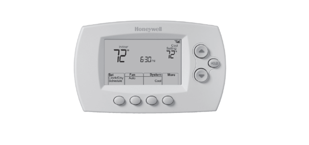
The Honeywell RTH6500WF Wi-Fi Programmable Thermostat User Guide is Honeywell Home’s owner manual for the RTH6500WF Smart Series 7-day programmable thermostat. The document number printed in the guide is 69-2715EF-07 (© 2018 Resideo Technologies, Inc.). It covers the touchscreen-style model with Wi-Fi and Total Connect Comfort, and it is the same guide used for the closely related RTH6580WF model. This page walks through what that guide contains and the facts most owners and installers look up.
Download rth6580wf1001-u-wi-fi-7-day-programmable-thermostat.pdf
Contents
- Before You Start: Box, Power, and Compatibility
- Installing and Wiring the RTH6500WF
- Connecting to Wi-Fi and Registering Online
- Daily Operation and Scheduling
- Special Features: Smart Response, Compressor Protection, Auto Changeover
- System Setup Functions
- Frequently Asked Questions
- Troubleshooting and Wi-Fi Error Codes
- Getting Help and Warranty
Before You Start: Box, Power, and Compatibility
The first page of the guide lists what comes in the box: the thermostat with the wallplate attached, screws and anchors, a Quick Start Guide, the Thermostat ID Card, wire labels, the User Guide, and a Quick Reference Card. The ID Card matters later: it carries the MAC ID and MAC CRC you need to register online.
Two compatibility rules decide whether this thermostat fits your system at all:
- It works with common 24-volt systems, including forced air, hydronic, heat pump, oil, gas, and electric.
- It does not work with millivolt systems (such as a gas fireplace) or with 120/240-volt systems (such as baseboard electric heat).
A C (common) wire is required. The guide states plainly that the C wire is the primary power source and that without it the thermostat will not power up; if you have no C wire, it points you to its alternate-wiring videos rather than improvising. Two safety notes are printed on the inside cover and should be read before mounting:
MERCURY NOTICE: Do not place your old thermostat in the trash if it contains mercury in a sealed tube. Contact the Thermostat Recycling Corporation at www.thermostat-recycle.org or 1-800-238-8192 for information on how and where to properly and safely dispose of your old thermostat.
NOTICE: To avoid possible compressor damage, do not run air conditioner if the outside temperature drops below 50°F (10°C).
Installing and Wiring the RTH6500WF
Installation runs step 1 through step 13 across pages 3 to 9. The guide’s own sequence:
- Switch the power off to the heating/cooling system at the breaker box or the system switch.
- Remove the old faceplate leaving wires connected, and photograph the connections before disconnecting anything.
- Label each wire with the supplied tags by its old terminal designation, never by wire color.
- Remove the old wallplate, then separate the new thermostat from its wallplate using the finger holds.
- Mount the new wallplate (drill 3/16-inch holes for drywall or 7/32-inch for plaster if new anchors are needed).
- Wire the thermostat, starting with the C wire, then attach the body, insert the quick-reference card, and restore power.
- Set the clock to the current day and time, and set the system type before testing.
Two wiring details are easy to miss and the guide calls them out. On heat pump systems, if the old thermostat had separate wires on AUX and E, both go into the single E/AUX terminal with no jumper. The K terminal is marked for future use, so leave it empty. For most conventional installs, keep the metal jumper between R and RC in place and remove it only if you must connect both R and RC wires.
The guide also warns that the heating/cooling system type must be set correctly or the thermostat can run the equipment wrongly. A conventional single-stage system can proceed straight to Wi-Fi setup; a multistage system, any heat pump, or a hydronic system requires you to set system function 1 first.
Connecting to Wi-Fi and Registering Online
Wi-Fi setup (pages 10 to 11) happens from the thermostat itself, which broadcasts a network named NewThermostat followed by numbers. You join that network from a tablet, laptop, or phone, then open a browser to reach the setup page (the guide’s address is http://192.168.1.1), pick your home network from the list, and enter its password. While joining, the screen flashes Wait for up to three minutes, then shows Wi-Fi Setup Connection Success and displays signal strength in the top-right corner.
Registration is separate from connecting (pages 12 to 13). To use remote access you create a Total Connect Comfort account at mytotalconnectcomfort.com, confirm the activation email, then add the thermostat using its unique MAC ID and MAC CRC. The guide notes these identifiers are on the Thermostat ID Card or on the back of the unit, and that they are not case sensitive. When registration succeeds, the site shows SUCCESS and the thermostat shows Setup Complete for about 90 seconds.
Software updates arrive on their own over Wi-Fi; during an update the screen shows Updating with a percentage, and your settings are kept.
Daily Operation and Scheduling
The home screen backlights for 8 seconds after any button. The buttons are the temperature up/down arrows, HOLD, and the Set Clock/Day/Schedule, Fan, and System soft-keys. The guide ships with four preset energy-saving periods:
| Period | Time | Default heat | Default cool |
|---|---|---|---|
| Wake | 6:00 am | 70° | 78° |
| Leave | 8:00 am | 62° | 85° |
| Return | 6:00 pm | 70° | 78° |
| Sleep | 10:00 pm | 62° | 82° |
Fan mode toggles between Auto (runs only during heating or cooling) and On (continuous). System mode cycles through Heat, Cool, Off, Auto, and, on heat pumps with auxiliary heat, Em Heat; the guide notes not every mode appears on every installation. To edit a schedule you press Set Clock/Day/Schedule then Set Schedule, and step through each day and period with the arrows, pressing Next and Done; check that the thermostat is already in the mode (Heat or Cool) you intend to program. A single arrow press is a temporary override that lasts until the next period, and Cancel restores the schedule; HOLD is the permanent override that turns the schedule off until you cancel it.
Special Features
Page 17 describes three behaviors that owners ask about most:
- Smart Response Technology learns how long the system takes to reach a setpoint and starts early so the room is comfortable at the scheduled time; the screen shows Recovery while it runs. Controlled by function 13.
- Compressor protection forces the compressor to wait a few minutes before restarting; Cool On (or Heat On on a heat pump) flashes during that wait.
- Auto changeover lets one Auto mode handle both heating and cooling, keeping the heat and cool setpoints at least 3 degrees apart. Controlled by function 12.
System Setup Functions
To enter system setup, press the Fan button and the up arrow together for about three seconds; the screen then shows a function number on the left and its option on the right, navigated with Next and adjusted with the arrows. The main functions listed on pages 18 to 19:
| Function | Purpose |
|---|---|
| 1 | System type (heat/cool, heat pump with or without backup, heat only, cool only, and the multistage combinations) |
| 2 | Heat pump changeover valve (O for cooling changeover, B for heating changeover) |
| 3 | Heating fan control (gas/oil versus electric) |
| 5, 6 | Heating cycle rate for stage 1 and stage 2 (matches equipment: steam/gravity, hot water or high-efficiency, standard gas/oil, electric) |
| 12 | Manual/auto changeover |
| 13 | Smart Response Technology on/off |
| 14 | Temperature format, Fahrenheit or Celsius |
| 16 | Schedule on/off (7-day programmable) |
| 36 | Device name for remote viewing |
| 38 | Wi-Fi on/off (turning it off removes the Wi-Fi Setup message) |
| 39 | Wi-Fi connection (set to 0 to disconnect the network) |
| 42 | Show or hide period and day on the home screen |
| 85, 90 | Restore the energy-saving schedule defaults; restore original settings (disconnects Wi-Fi and clears customizations) |
Frequently Asked Questions
Page 20 answers these common ones:
- Yes, the thermostat keeps running your heating and cooling with or without Wi-Fi; remote features are the only thing lost.
- The MAC ID and MAC CRC are on the ID Card in the box or on the back of the thermostat, and each unit’s pair is unique.
- If you cannot see the Wi-Fi Setup page, you are probably connected to the router and not the thermostat; reconnect to the thermostat.
- Signal range can be extended with a Wi-Fi repeater or by configuring a standard router as a repeater.
Troubleshooting and Wi-Fi Error Codes
Pages 21 and 22 carry the guide’s own troubleshooting list. It is reproduced here with only what the manual states.
| Problem | What the manual advises |
|---|---|
| Display is blank | Check and reset the circuit breaker; make sure the heating/cooling power switch is on; make sure the furnace door is closed securely; make sure the C wire is connected (page 6). |
| Cannot change system to Cool | Check function 1 (System Type) so it matches your equipment. |
| Fan does not run when heat is called | Check function 3 (Heating Fan Control) for the right gas/oil versus electric setting. |
| Cool On or Heat On is flashing | Compressor protection is engaged; wait five minutes for a safe restart. |
| Heat pump blows cool in heat mode, or warm in cool mode | Check function 2 (Heat Pump Changeover Valve) is set for your O or B valve. |
| Heating or cooling does not respond | Set System to Heat and make sure the setpoint is above the indoor temperature (or Cool and below), then check the breaker, power switch, and furnace door, and wait five minutes. |
| Heating runs in cool mode, or heat and cool run together | Check function 1; pull the thermostat off the wallplate and confirm bare wires are not touching; verify the wiring. |
The Wi-Fi error codes on page 21 behave the same way: the manual’s code, meaning, and its stated action.
| Code | What the manual says to do |
|---|---|
| E01 | Router lost power during Wi-Fi Setup; confirm the router is powered and working. |
| E02 | Invalid Wi-Fi password (shows for 30 seconds, then returns to Wi-Fi Setup); re-enter the correct password. |
| E42 | Router not issuing an IP address; wait up to 30 minutes, restart the thermostat off the wallplate for 10 seconds, and confirm the router assigns addresses. |
| E43 | No internet connection; make sure the internet cable is plugged in and reboot the router. |
| E99 | General error; take the thermostat off the wallplate for 10 seconds, then reattach. |
If the no-Wi-Fi icon replaces the signal bars, the guide’s Lost Signal steps are to confirm Wi-Fi works on another device (and call your internet provider if not), move the router, and restart the thermostat by pulling it off the wallplate for 10 seconds before repeating the Wi-Fi setup.
Getting Help and Warranty
The guide directs owners to honeywellhome.com, and to call 1-855-733-5465 before returning the thermostat to the store. Additional FAQs live at honeywellhome.com/support. The document itself is 69-2715EF-07, and the limited warranty statement is on page 24 of the guide. For any service call, note the model number and the MAC ID/CRC, and, if a system-type problem is suspected, the current value of function 1, because those are the details the guide asks you to have ready.