Category Archives: Thermostat

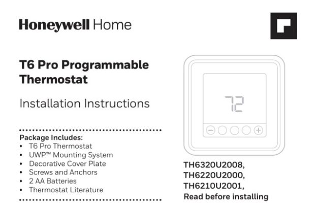
Honeywell T6 Pro Programmable Thermostat Installation Manual

Honeywell T6 Pro Programmable Thermostat Installation Manual

The Honeywell T6 Pro Programmable Thermostat Installation Manual is Honeywell Home’s technician-facing booklet for the T6 Pro touchscreen programmable thermostat. The current printing carries document number 33-00181EFS (revision 33-00181EFS-19, M.S. Rev. 05-22, © 2022 Resideo Technologies, Inc.). The English section runs pages 1 to 14, with French following and Spanish at the back, and the three model numbers it covers are TH6320U2008, TH6220U2000, and TH6210U2001.

Where the guide says “shaded areas apply only to TH6320U / TH6220U” or “(TH6320U only),” read that as a real limit: the smaller TH6210U is a single-compressor model and does not carry the second-stage, sensor, and dual-fuel options. The installer-setup table below shows which functions are gated to a specific model so you do not chase an option that does not exist on the unit in front of you.

Download Honeywell T6 Pro Installation Instructions Manual (PDF)

Contents

Before You Start: Box, Tools, and Power

Page 1 lists what is in the box: the T6 Pro thermostat, the UWP™ Mounting System, a decorative cover plate, screws and anchors, two AA batteries, and the thermostat literature. The cover plate comes in two physical shapes and the guide walks each one:

  • Square cover plate. Separate the cover plate from its mounting plate, fix the mounting plate to the wall using any of its eight screw holes, hang the UWP on the top hook, snap the bottom of the UWP in, then snap the cover plate onto the mounting plate.
  • Rectangular cover plate. Mount the cover plate directly to the wall with any of its six screw holes, hang the UWP on its top hook, and snap the UWP bottom into place.

Drill sizes are fixed by anchor color: 7/32 in (5.6 mm) for the red anchors and 3/16 in (4.8 mm) for the yellow anchors, with #8 1-1/2 in (38 mm) screws for red and #6 1-1/2 in (38 mm) for yellow. Page 2 opens every mounting path with the same rule: turn the power off at the breaker box or the system switch before you do anything else.

Terminals, Power Options, and the Slider Tabs

The UWP carries a wide set of terminals, but not all of them are live on the T6 Pro. The guide is explicit about which are used and which are “Not used for T3 thermostat” on the smaller variants. This is the reference table:

Terminal Function
R 24 VAC power from the heating transformer (jumpable via R slider tab)
Rc 24 VAC power from the cooling transformer (jumpable via R slider tab)
C 24 VAC common; on two-transformer systems, from the cooling transformer
W Heat stage 1. Do not use this terminal for heat pump applications
W2 / AUX Auxiliary heat, or Heat stage 2 on conventional multistage systems
Y Compressor contactor, stage 1
Y2 Compressor contactor, stage 2
G Fan
O/B Heat pump changeover valve
E Emergency heat (TH6320U)
L/A Heat pump fault input; the common (C) wire is required when L/A is used
S Wired indoor or outdoor sensor input (TH6320U / TH6220U only)
K, U Unused

The R/Rc slider tab is the built-in jumper on the UWP. If you have only one R wire, no matter whether it landed on R, Rc, or Rh on the old base, leave the slider in the up (one-wire) position. If you have separate wires on R and Rc, move the slider to the down (two-wire) position. The guide adds one T6 Pro specific instruction: the U-terminal slider tabs should be left in place.

Power options. The R and C terminals are the primary 24 VAC supply; the C terminal is optional only because the two AA batteries can carry the thermostat on their own, and the guide still recommends wiring C. Insert the two AA cells for primary power on battery-only installs, or as backup power alongside 24 VAC.

Wiring Diagrams by System Type

Pages 4 and 5 print the wiring diagrams the installer matches to the equipment. The conventional set on page 4 covers 1H/1C with one or two transformers, heat-only, heat-only with fan, heat-only Series 20 (radiant zone valve wiring), heat-only power-open zone valve, cool-only, and 2H/2C with one transformer. The heat pump set on page 5 covers 1H/1C, 2H/1C with auxiliary and emergency heat, 2H/2C, 3H/2C, and Dual Fuel. Model limits the guide prints:

  • The second compressor stage (Y2) and the auxiliary/emergency heat pair (AUX and E) apply on the larger heat-pump models. The 3H/2C and the Y2-equipped Dual Fuel arrangements are called out as TH6320U only.
  • Where the old base has separate wires on AUX and E, both go into the combined E/AUX terminal; a wire that ran to AUX with a jumper over to E is handled the same way and needs no jumper on the T6 Pro.
  • Wire specification printed on both pages is 18- to 22-gauge thermostat wire; shielded cable is not required.

The Series 20 and power-open-zone-valve arrangements come with an ISU pairing: in the Installer Setup, set Heat system type to Radiant Heat and Cool stages to 0 (notes [5]). The 2H/2C conventional system uses note [6]: in Installer Setup, set system type to 2 Heat / 2 Cool Conventional. Reversing valve polarity is note [7]: set the changeover valve in Installer Setup to O (cool changeover) or B (heat changeover). The heat-pump stage counts are notes [8], [9], and [10]; they pick which compressor and backup-heat combination ISU 200, 220, 221, and 255 have to match.

Mounting the UWP and the Thermostat

Pages 2 and 6 combine into a short physical sequence. Turn off the breaker or system switch. Position the UWP, level it, mark the holes, drill to the anchor color, and tap the anchors flush. Pull open the UWP door, feed the wires through the wiring hole, place the UWP on the anchors, tighten the mounting screws with the correct screw size for the anchor color until the plate no longer moves, and close the door. On page 6 the guide tells you to push any excess wire back into the wall opening, close the door so it does not bulge, align and snap the thermostat onto the UWP, and only then restore power at the breaker or switch.

With power back on, page 6 covers the first-time set of clock and date. Press Menu, arrow to TIME (12 or 24 hour format, hour, minutes), then DATE (year, month, day). Pressing Select at each step saves and advances.

Installer Setup (ISU) Reference

Page 8 opens the ISU section with the entry key: press and hold CENTER together with the second button shown on page 8 for about three seconds to enter the advanced menu, then Select to enter ISU. Cycle options with Select, change values with the up/down arrows, and press Home when you are done to save and return to the Home screen. The guide’s full list runs pages 8 to 10; defaults shown in bold are the ones the manual marks as the shipped values. Model-gated rows are called out. The functions installers change most:

ISU Name Options and model notes
120 Scheduling options 0 non-programmable, 2 = 5-2, 3 = 5-1-1, 4 = 7-day
125 Temperature indication scale 0 = Fahrenheit, 1 = Celsius
130 Outdoor sensor 0 none, 1 wired (TH6320U / TH6220U only)
200 Heating system type 1 conventional forced air, 2 heat pump, 3 radiant, 5 none (cool only)
205 Heating equipment type Forced air 1-5 (standard gas, high-efficiency gas, oil, electric, hot-water fan coil); heat pump 7 air-to-air or 8 geothermal; radiant 9 hot water or 12 steam
218 Reversing valve O/B 0 = O (energized in Cool), 1 = B (energized in Heat)
220 Cool / compressor stages 0, 1, or 2 (TH6210U is single-compressor only; TH6220U on a heat pump is also limited to one)
221 Heat / backup heat stages Heat 1 or 2; backup 0 or 1
230 Fan control in Heat 1 equipment controls fan, 2 thermostat controls fan (shown when ISU 205 is electric forced air or fan coil)
253 Aux/E terminal control 0 drive both together, 1 independent; fixed at 0 on every model except TH6320U
255 Backup heat source (heat pump) 1 electric forced air, 2 gas/oil (fossil) forced air (TH6320U / TH6220U only)
256 Emergency heat source 1 electric forced air, 2 gas/oil (fossil) forced air (TH6320U only)
260 External fossil fuel kit 0 thermostat controls backup heat, 1 external kit controls it (TH6320U / TH6220U only)
300 System changeover 0 manual, 1 automatic (turns on the Auto system mode on the Home screen)
303 Auto changeover differential 0 to 5 °F (0 to 2.5 °C); the guide notes this is not deadband, whose value is fixed at 0 °F by firmware
340 Backup heat droop 0 comfort or 2 to 15 °F; the comfort setting is available only when ISU 255 backup heat is electric
350 Upstage timer to backup heat Off, 30 min up to 16 hours
355, 356 Compressor lockout / balance point and outdoor lockout backup heat Off or 5-60 °F / 5-65 °F in 5 °F steps; use a wired outdoor sensor to configure (TH6320U / TH6220U)
365, 366 Compressor cycle rate, stages 1 and 2 1 to 6 cycles per hour
370, 371 Heating cycle rate, stages 1 and 2 1 to 12 CPH
375 Heating cycle rate auxiliary 1 to 12 CPH
378 Heating cycle rate emergency 1 to 12 CPH (TH6320U only)
387 Compressor protection Off, or 1 to 5 minutes of minimum off time
425 Adaptive Intelligent Recovery 0 no, 1 yes; runs equipment early so the room hits the setpoint on schedule
430, 431 Minimum cool setpoint, maximum heat setpoint Cool 50 to 99 °F (default 50 °F), Heat 40 to 90 °F (default 90 °F)
435 Keypad lockout Series 0-6 (older T6): 0 none, 1 partial, 2 full. Series 7 (current): 0 disabled, 1 enabled; when disabled the menu lockout option disappears entirely
500, 515, 520 Indoor sensor wiring, type, and control source TH6320U / TH6220U only: 500 no/yes wired; 515 10k or 20k; 520 1 thermostat only, 2 wired only, or 3 average
702, 711, 712 Air filter count and each filter’s replacement reminder 0 to 2 filters; interval per filter from 0 (off) through run-time days (10 to 150) and calendar days/months (30 days up to 15 months)
1400, 1401 Backlighting and its brightness 0 on demand, 1 continuous (needs a C wire); brightness 1 to 5 shown only when continuous is selected
1410, 1415 Clock format and daylight saving time 12 or 24 hour; DST 0 off, 1 on
1420 Temperature display offset -3 to +3 °F or -1.5 to +1.5 °C (0 means the display is unaltered)

Installer System Test

Page 11 walks the same entry path as ISU, then arrow to TEST and press Select. Inside the test, arrow to switch between Heat, Cool, Fan, Em Heat, and Ver (the firmware version screen). Press Select and use the arrows to bring each stage on and off one at a time, and press Home to exit. The status codes the guide prints: Heat 0 all off, 1 stage 1 on, 2 stage 2 on, 3 stage 3 on; Cool 0 all off, 1 stage 1 on, 2 stage 2 on; Em Heat 0 off, 1 on; Fan 0 off, 1 on. The stage 2, stage 3, and the Em Heat rows apply to the larger heat-pump models; on the TH6210U and other single-stage conventional setups those steps do not appear.

Specifications and Electrical Ratings

Page 12 is the specification block:

Item Value from the manual
Heat setpoint range 40 to 90 °F (4.5 to 32.0 °C)
Cool setpoint range 50 to 99 °F (10.0 to 37.0 °C)
Working ambient 32 to 120 °F (0 to 48.9 °C)
Operating ambient 37 to 102 °F (2.8 to 38.9 °C)
Shipping temperature -20 to 120 °F (-28.9 to 48.9 °C)
Operating relative humidity 5% to 90% non-condensing
Physical size (H × W × D) 4-1/16 in × 4-1/16 in × 1-5/32 in (103.5 × 103.5 × 29 mm)
Terminal voltage, all outputs 20 to 30 VAC, 50/60 Hz
Running current, W / W2 (Aux) / Y / Y2 0.02 to 1.0 A
Running current, E / G / O/B / L/A 0.02 to 0.5 A
Wire gauge, unshielded 18 to 22

Safety and Disposal Notices

Page 14 prints four cautions that belong in any installer handoff. They are quoted here exactly:

CAUTION: ELECTRICAL HAZARD. Can cause electrical shock or equipment damage. Disconnect power before beginning installation.

CAUTION: EQUIPMENT DAMAGE HAZARD. Compressor protection is bypassed during testing. To prevent equipment damage, avoid cycling the compressor quickly.

CAUTION: MERCURY NOTICE. If this product is replacing a control that contains mercury in a sealed tube, do not place the old control in the trash. Contact your local waste management authority for instructions regarding recycling and proper disposal.

CAUTION: ELECTRONIC WASTE NOTICE. The product and batteries should not be disposed of with other household waste. Check for the nearest authorized collection centers or authorized recyclers. The correct disposal of end-of-life equipment will help prevent negative consequences for the environment and human health.

Troubleshooting

Page 13 is the guide’s own troubleshooting table. It is reproduced below with only what the manual states.

Problem What the manual advises
Display is blank Check the circuit breaker and reset if necessary. Confirm the power switch for the heating and cooling system is on. Confirm the furnace door is closed securely. Confirm two fresh AA alkaline batteries are correctly installed (see page 3).
Heating or cooling system does not respond Press Mode to set System to Heat (page 7) and confirm the desired temperature is above the indoor temperature. To test cooling, press Mode to set System to Cool and confirm the desired temperature is below the indoor temperature. Check the circuit breaker and reset if necessary. Confirm the heating and cooling power switch is on. Confirm the furnace door is closed securely. Wait five minutes for the system to respond.
Temperature settings do not change Confirm the setpoints are inside the ranges the guide lists: heat 40 to 90 °F (4.5 to 32.0 °C), cool 50 to 99 °F (10.0 to 37.0 °C).
“Cool On” or “Heat On” is flashing Compressor protection is engaged. Wait five minutes for a safe restart without damaging the compressor.
Auxiliary heat runs during cooling For heat pump systems, verify there is no wire attached to W on the UWP. See “Wiring heat pump systems” on page 5.
Cool runs on a call for heat For heat pump systems, verify there is no wire attached to W on the UWP. See “Wiring heat pump systems” on page 5.

Getting Help

The back-page customer assistance block on page 14 points installers to customer.resideo.com and to Resideo Customer Care at 1-800-468-1502, and the FCC statement is available at the same Resideo support path. The mailing address printed in the same footer is Resideo Technologies Inc., 1985 Douglas Drive North, Golden Valley, MN 55422. The identifier to quote when you call is the document marking on the booklet cover, 33-00181EFS-19, plus the model number on the back of the thermostat (TH6320U2008, TH6220U2000, or TH6210U2001).

Because this booklet is the installation guide, homeowner-side operation (schedules, overrides, alerts, and cleaning) is documented in the matching T6 Pro user guide, not here. If your question is about how the thermostat behaves day to day, ask the installer for that guide or download it separately.
Honeywell RTH6500WF Wi-Fi Programmable Thermostat User Guide

Honeywell RTH6500WF Wi-Fi Programmable Thermostat User Guide

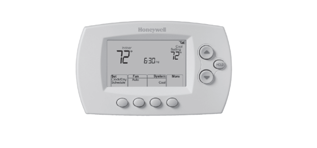
The Honeywell RTH6500WF Wi-Fi Programmable Thermostat User Guide is Honeywell Home’s owner manual for the RTH6500WF Smart Series 7-day programmable thermostat. The document number printed in the guide is 69-2715EF-07 (© 2018 Resideo Technologies, Inc.). It covers the touchscreen-style model with Wi-Fi and Total Connect Comfort, and it is the same guide used for the closely related RTH6580WF model. This page walks through what that guide contains and the facts most owners and installers look up.

Download rth6580wf1001-u-wi-fi-7-day-programmable-thermostat.pdf

Contents

Before You Start: Box, Power, and Compatibility

The first page of the guide lists what comes in the box: the thermostat with the wallplate attached, screws and anchors, a Quick Start Guide, the Thermostat ID Card, wire labels, the User Guide, and a Quick Reference Card. The ID Card matters later: it carries the MAC ID and MAC CRC you need to register online.

Two compatibility rules decide whether this thermostat fits your system at all:

  • It works with common 24-volt systems, including forced air, hydronic, heat pump, oil, gas, and electric.
  • It does not work with millivolt systems (such as a gas fireplace) or with 120/240-volt systems (such as baseboard electric heat).

A C (common) wire is required. The guide states plainly that the C wire is the primary power source and that without it the thermostat will not power up; if you have no C wire, it points you to its alternate-wiring videos rather than improvising. Two safety notes are printed on the inside cover and should be read before mounting:

MERCURY NOTICE: Do not place your old thermostat in the trash if it contains mercury in a sealed tube. Contact the Thermostat Recycling Corporation at www.thermostat-recycle.org or 1-800-238-8192 for information on how and where to properly and safely dispose of your old thermostat.

NOTICE: To avoid possible compressor damage, do not run air conditioner if the outside temperature drops below 50°F (10°C).

Installing and Wiring the RTH6500WF

Installation runs step 1 through step 13 across pages 3 to 9. The guide’s own sequence:

  1. Switch the power off to the heating/cooling system at the breaker box or the system switch.
  2. Remove the old faceplate leaving wires connected, and photograph the connections before disconnecting anything.
  3. Label each wire with the supplied tags by its old terminal designation, never by wire color.
  4. Remove the old wallplate, then separate the new thermostat from its wallplate using the finger holds.
  5. Mount the new wallplate (drill 3/16-inch holes for drywall or 7/32-inch for plaster if new anchors are needed).
  6. Wire the thermostat, starting with the C wire, then attach the body, insert the quick-reference card, and restore power.
  7. Set the clock to the current day and time, and set the system type before testing.

Two wiring details are easy to miss and the guide calls them out. On heat pump systems, if the old thermostat had separate wires on AUX and E, both go into the single E/AUX terminal with no jumper. The K terminal is marked for future use, so leave it empty. For most conventional installs, keep the metal jumper between R and RC in place and remove it only if you must connect both R and RC wires.

The guide also warns that the heating/cooling system type must be set correctly or the thermostat can run the equipment wrongly. A conventional single-stage system can proceed straight to Wi-Fi setup; a multistage system, any heat pump, or a hydronic system requires you to set system function 1 first.

Connecting to Wi-Fi and Registering Online

Wi-Fi setup (pages 10 to 11) happens from the thermostat itself, which broadcasts a network named NewThermostat followed by numbers. You join that network from a tablet, laptop, or phone, then open a browser to reach the setup page (the guide’s address is http://192.168.1.1), pick your home network from the list, and enter its password. While joining, the screen flashes Wait for up to three minutes, then shows Wi-Fi Setup Connection Success and displays signal strength in the top-right corner.

Registration is separate from connecting (pages 12 to 13). To use remote access you create a Total Connect Comfort account at mytotalconnectcomfort.com, confirm the activation email, then add the thermostat using its unique MAC ID and MAC CRC. The guide notes these identifiers are on the Thermostat ID Card or on the back of the unit, and that they are not case sensitive. When registration succeeds, the site shows SUCCESS and the thermostat shows Setup Complete for about 90 seconds.

Software updates arrive on their own over Wi-Fi; during an update the screen shows Updating with a percentage, and your settings are kept.

Daily Operation and Scheduling

The home screen backlights for 8 seconds after any button. The buttons are the temperature up/down arrows, HOLD, and the Set Clock/Day/Schedule, Fan, and System soft-keys. The guide ships with four preset energy-saving periods:

Period Time Default heat Default cool
Wake 6:00 am 70° 78°
Leave 8:00 am 62° 85°
Return 6:00 pm 70° 78°
Sleep 10:00 pm 62° 82°

Fan mode toggles between Auto (runs only during heating or cooling) and On (continuous). System mode cycles through Heat, Cool, Off, Auto, and, on heat pumps with auxiliary heat, Em Heat; the guide notes not every mode appears on every installation. To edit a schedule you press Set Clock/Day/Schedule then Set Schedule, and step through each day and period with the arrows, pressing Next and Done; check that the thermostat is already in the mode (Heat or Cool) you intend to program. A single arrow press is a temporary override that lasts until the next period, and Cancel restores the schedule; HOLD is the permanent override that turns the schedule off until you cancel it.

Special Features

Page 17 describes three behaviors that owners ask about most:

  • Smart Response Technology learns how long the system takes to reach a setpoint and starts early so the room is comfortable at the scheduled time; the screen shows Recovery while it runs. Controlled by function 13.
  • Compressor protection forces the compressor to wait a few minutes before restarting; Cool On (or Heat On on a heat pump) flashes during that wait.
  • Auto changeover lets one Auto mode handle both heating and cooling, keeping the heat and cool setpoints at least 3 degrees apart. Controlled by function 12.

System Setup Functions

To enter system setup, press the Fan button and the up arrow together for about three seconds; the screen then shows a function number on the left and its option on the right, navigated with Next and adjusted with the arrows. The main functions listed on pages 18 to 19:

Function Purpose
1 System type (heat/cool, heat pump with or without backup, heat only, cool only, and the multistage combinations)
2 Heat pump changeover valve (O for cooling changeover, B for heating changeover)
3 Heating fan control (gas/oil versus electric)
5, 6 Heating cycle rate for stage 1 and stage 2 (matches equipment: steam/gravity, hot water or high-efficiency, standard gas/oil, electric)
12 Manual/auto changeover
13 Smart Response Technology on/off
14 Temperature format, Fahrenheit or Celsius
16 Schedule on/off (7-day programmable)
36 Device name for remote viewing
38 Wi-Fi on/off (turning it off removes the Wi-Fi Setup message)
39 Wi-Fi connection (set to 0 to disconnect the network)
42 Show or hide period and day on the home screen
85, 90 Restore the energy-saving schedule defaults; restore original settings (disconnects Wi-Fi and clears customizations)

Frequently Asked Questions

Page 20 answers these common ones:

  • Yes, the thermostat keeps running your heating and cooling with or without Wi-Fi; remote features are the only thing lost.
  • The MAC ID and MAC CRC are on the ID Card in the box or on the back of the thermostat, and each unit’s pair is unique.
  • If you cannot see the Wi-Fi Setup page, you are probably connected to the router and not the thermostat; reconnect to the thermostat.
  • Signal range can be extended with a Wi-Fi repeater or by configuring a standard router as a repeater.

Troubleshooting and Wi-Fi Error Codes

Pages 21 and 22 carry the guide’s own troubleshooting list. It is reproduced here with only what the manual states.

Problem What the manual advises
Display is blank Check and reset the circuit breaker; make sure the heating/cooling power switch is on; make sure the furnace door is closed securely; make sure the C wire is connected (page 6).
Cannot change system to Cool Check function 1 (System Type) so it matches your equipment.
Fan does not run when heat is called Check function 3 (Heating Fan Control) for the right gas/oil versus electric setting.
Cool On or Heat On is flashing Compressor protection is engaged; wait five minutes for a safe restart.
Heat pump blows cool in heat mode, or warm in cool mode Check function 2 (Heat Pump Changeover Valve) is set for your O or B valve.
Heating or cooling does not respond Set System to Heat and make sure the setpoint is above the indoor temperature (or Cool and below), then check the breaker, power switch, and furnace door, and wait five minutes.
Heating runs in cool mode, or heat and cool run together Check function 1; pull the thermostat off the wallplate and confirm bare wires are not touching; verify the wiring.

The Wi-Fi error codes on page 21 behave the same way: the manual’s code, meaning, and its stated action.

Code What the manual says to do
E01 Router lost power during Wi-Fi Setup; confirm the router is powered and working.
E02 Invalid Wi-Fi password (shows for 30 seconds, then returns to Wi-Fi Setup); re-enter the correct password.
E42 Router not issuing an IP address; wait up to 30 minutes, restart the thermostat off the wallplate for 10 seconds, and confirm the router assigns addresses.
E43 No internet connection; make sure the internet cable is plugged in and reboot the router.
E99 General error; take the thermostat off the wallplate for 10 seconds, then reattach.

If the no-Wi-Fi icon replaces the signal bars, the guide’s Lost Signal steps are to confirm Wi-Fi works on another device (and call your internet provider if not), move the router, and restart the thermostat by pulling it off the wallplate for 10 seconds before repeating the Wi-Fi setup.

Getting Help and Warranty

The guide directs owners to honeywellhome.com, and to call 1-855-733-5465 before returning the thermostat to the store. Additional FAQs live at honeywellhome.com/support. The document itself is 69-2715EF-07, and the limited warranty statement is on page 24 of the guide. For any service call, note the model number and the MAC ID/CRC, and, if a system-type problem is suspected, the current value of function 1, because those are the details the guide asks you to have ready.

Honeywell T6 Pro Programmable Thermostat User Manual

Honeywell T6 Pro Programmable Thermostat User Manual

The Honeywell T6 Pro Programmable Thermostat user guide is available as a PDF for models TH6320U2008, TH6220U2000, and TH6210U2001.

The guide explains how to operate the thermostat, change temperature settings, program a schedule, and use temporary or permanent Hold. It also covers the basic controls and system settings needed for everyday use.

Package Includes:

• T6 Pro Thermostat
• UWP Mounting System
• Honeywell Standard Installation Adapter (J-box adapter)
• Honeywell Decorative Cover Plate – Small; size 4-49/64 in x 4-49/64 in x 11/32 in (121 mm x 121 mm x 9 mm)
• Screws and anchors
• 2 AA Batteries
• Installation Instructions and User Guide

Models covered: TH6320U2008, TH6220U2000, TH6210U2001
File format: PDF
Language: English

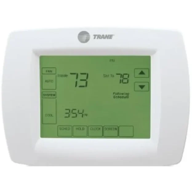
Trane TCONT802AS32DA

Trane TCONT802AS32DA Installation Instructions Manual

Download the installation instructions for the Trane TCONT802AS32DA touchscreen comfort control. The document also covers the related TCONT803AS32DA model.

Document number: 18-HD25D19-3
Format: PDF
Language: English

About This Manual

This installation manual is intended for technicians installing or replacing a compatible Trane comfort control. It covers thermostat placement, wiring, equipment setup, and installation checks. The exact configuration depends on the heating and cooling system connected to the control.

The instructions include guidance on thermostat location. For reliable temperature readings, placement should follow the manufacturer’s recommendations and avoid areas affected by drafts or unusual heat sources.

Online Reading & Download Installation Instructions

Skip to PDF content

Before beginning installation, confirm the model number and follow the complete instructions for the equipment being serviced. Thermostat wiring and system configuration should be handled by a qualified HVAC technician.

Honeywell TH6210U2001 T6 Pro Programmable Thermostat User Guide

Honeywell TH6210U2001 T6 Pro Programmable Thermostat User Guide

This page walks through the Honeywell TH6210U2001 T6 Pro Programmable Thermostat User Guide (document 00182EFS, Rev. 04-22). The T6 Pro is a five-button programmable thermostat for 20 to 30 VAC heating and cooling systems; the same guide also covers the TH6220U2000 and TH6320U2008. The points below follow the manual and cite its pages, and the PDF is linked here. Work from the guide whenever a screen or wire does not match what this summary shows.

Download TH6210U2001 T6 Pro User Manual (PDF)

Table of Contents

What the T6 Pro Is

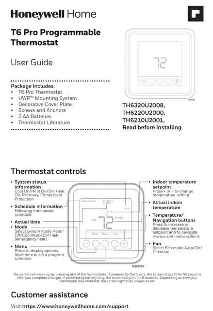
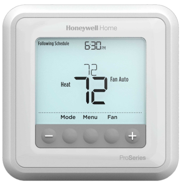
The T6 Pro (TH6210U2001) is a programmable thermostat with a backlit screen and five physical buttons. From the guide’s overview and controls panel:

  • Programmable, four periods a day. Wake, Away, Home and Sleep, with different settings for weekdays and weekends.
  • Five buttons. Menu, Select, and the + and − navigation buttons, plus Mode and Fan.
  • Mode selection. Auto, Heat, Cool, EM Heat (emergency heat) and Off.
  • Status display. Cool On, Heat On, Em Heat On, Recovery and Compressor Protection are shown as they apply.

The guide notes the thermostat works with 20 to 30 VAC systems, and the electrical ratings table lists terminals including W, W2 (Aux) and Y2 alongside C, so a single- or multi-stage layout may apply depending on your model in this family.

Controls and Buttons

  • Menu. Opens the options list; this is also where you start a program schedule.
  • Select. Confirms the highlighted entry as you move through menus.
  • + and −. Raise or lower the temperature setpoint and move through menu items.
  • Mode. Cycles the thermostat between Auto, Heat, Cool, EM Heat and Off.
  • Fan. Switches the fan between Auto, On and Circulate.

Pressing any of the five buttons wakes the screen. When a C-wire supply is present, the backlight stays on and the screen does not sleep; on battery-only installations the display dims after a short period (the guide notes roughly eight seconds of lit display on battery).

Modes and Fan Settings

  • Auto. The thermostat chooses heating or cooling to reach the setpoint.
  • Heat. Heating only.
  • Cool. Cooling only.
  • EM Heat. Emergency heat on a heat-pump system that has auxiliary or backup heat.
  • Off. Both systems off.

Fan choices: Auto runs the blower only during heating or cooling; On runs it continuously; Circulate runs it for a scheduled slice of each hour to keep air moving.

Setting the Time and Date

The guide has you press Menu, then arrow down to TIME, then press Select to enter the clock. You pick 12- or 24-hour display, then adjust the hour and minutes with the + and − buttons, confirming each entry with Select. From the same Menu you reach DATE to set the year, month and day. Do this before you rely on any schedule; the periods trigger on the clock, not the temperature.

Programming the Schedule

Press Menu, then arrow to PROG and press Select. Choose ON to enable the program. You then pick the day or group of days to edit, then a period (Wake, Away, Home or Sleep), then set the time and the temperature for that period. Repeat for each period, and switch to the other day group to set it separately. Wake is when you get up and get ready for the day; Away is when you leave; Home is when you return in the evening; Sleep is overnight. The guide’s pre-set times are Wake 6:00 AM, Away 8:00 AM, Home 6:00 PM and Sleep 10:00 PM, and it recommends starting from the pre-sets because they can reduce energy cost. If you do not want a schedule at all, set PROG to OFF.

Overriding the Schedule

For a one-off change, press + or − on the home screen; the change lasts until the next scheduled period. To hold a temperature indefinitely, use the hold option in the menu; the guide shows how to return to the program from the same screen. Because heating and cooling are programmed separately, change the Mode if you need to adjust the other season.

Filter Reminders and Alerts

An alert icon appears on the home screen when a reminder is due. Press Menu, arrow to ALRT, and press Select to see which alerts are active. Press Select again to snooze the reminder for 7 days, or arrow to CLER and press Select to clear it. The guide notes some alerts cannot be snoozed or cleared; if that happens, service may be needed and you should call your heating and cooling professional.

Batteries

Two AA alkaline batteries power the T6 Pro. If the thermostat is wired to a C (AC) supply, the batteries are optional and act as backup power; if it is not C-wired, the batteries are required. Install fresh batteries as soon as the low-battery icon appears on the home screen. The guide notes the icon shows up about two months before the batteries are depleted, and recommends replacing them at least once a year or before a trip longer than a month. If new batteries go in within about two minutes of removing the old ones, the time and day stay set; the schedule and other settings are held in memory.

Troubleshooting (From the Guide)

These are the guide’s own troubleshooting items (p.7-8). Only what the manual lists; if your issue is not here, use the Customer Assistance line at the end.

Problem What the guide says to do
Display is blank Check and reset the circuit breaker; confirm the power switch at the heating/cooling system is on; make sure the furnace door is closed securely; install fresh AA alkaline batteries.
Heating or cooling does not respond Press Mode to set Heat (or Cool), and make sure the setpoint is higher (or lower) than the indoor temperature. Then check the circuit breaker, the system power switch and the furnace door, and wait about 5 minutes for the system to respond.
Temperature settings do not change Bring the setpoint inside the allowed ranges: Heat 40°F to 90°F (4.5°C to 32.0°C); Cool 50°F to 99°F (10.0°C to 37.0°C).
“Cool On” or “Heat On” is flashing Compressor protection is engaged. Wait about 5 minutes so the compressor can restart without damage.
A reminder keeps appearing Snooze from the ALRT menu for 7 days, or clear it with CLER; some alerts cannot be snoozed or cleared, and a service call may be needed.

Specifications and Support

  • Models covered by this guide: TH6210U2001, TH6220U2000 and TH6320U2008 (T6 Pro family).
  • Voltage: 20 to 30 VAC (the guide’s electrical ratings).
  • Program periods: four per day (Wake, Away, Home, Sleep), with weekday and weekend settings.
  • Modes: Auto, Heat, Cool, EM Heat and Off.
  • Fan modes: Auto, On and Circulate.
  • Setpoint range: Heat 40°F to 90°F; Cool 50°F to 99°F.
  • Power: two AA alkaline batteries; batteries optional when a C wire supplies AC power.
  • Compressor protection: built-in, about 5 minutes; shown as “Cool On” or “Heat On” flashing.
  • Warranty: 1-year limited (see the guide).
  • Support: https://www.honeywellhome.com/support; Resideo Technologies, Inc., 1985 Douglas Drive North, Golden Valley, MN 55422.

For exact dimensions, mounting height, torque and the wiring terminal-by-terminal table, the guide’s Installation Instructions and the wiring diagrams on the later pages are the authority; this page is a companion to that document.

FAQ

How many periods per day does the T6 Pro program?

Four: Wake, Away, Home and Sleep. You can set them differently for weekdays and weekends.

Does the T6 Pro have an emergency heat setting?

Yes. On heat-pump systems with auxiliary or backup heat, the Mode cycle includes EM Heat, which the guide also shows in the status display as “Em Heat On”.

Do I need a C wire?

Not strictly. The T6 Pro runs on two AA alkaline batteries; if a C wire supplies AC power, the batteries are backup and the display stays lit. Without a C wire the batteries are required and the screen dims after a few seconds when idle.

Why does “Cool On” or “Heat On” keep flashing?

Compressor protection is engaged. The guide’s troubleshooting section says to wait about five minutes so the compressor can restart safely.

Why do my setpoints stop at 40 or 90 degrees?

You hit the programming range. The guide lists Heat 40°F to 90°F and Cool 50°F to 99°F; anything outside is rejected while you set the schedule.

Honeywell Home T3 Pro Thermostat Installation Instructions Manual

Honeywell Home T3 Pro Thermostat Installation Instructions Manual

This page is for the Honeywell Home T3 Programmable Thermostat Installation Manual. The matching PDF on honeywellmanual.com is T3 Pro Thermostat Installation Instructions, document number 33-00520EFS-01 (M.S. 04-20, © 2020 Resideo Technologies, Inc.), a 36-page trilingual booklet with English on pages 1 to 12, French on pages 13 to 24, and Spanish on pages 25 to 36.

A note before you open the file: the “T3 Pro” line covers Honeywell Home’s non-programmable touchscreen thermostat, models TH3110U2008 and TH3210U2004. It has no weekly schedule; on the owner’s side you get a System mode selector, a Fan mode selector, and Installer Setup (ISU) for the technician. If the box says a programmable Honeywell Home model in the T5, T6, T9, or Wi-Fi 9000 family, this is the wrong document, and the model number printed behind the wallplate is the number to search instead.

Download T3 Pro Thermostat Installation Manual (PDF)

Contents

What Is in the Box

Page 1 lists the package contents directly. The T3 Pro box contains the thermostat itself, a UWP™ Mounting System, a small decorative cover plate sized 4.72″ H x 5.9″ W (120 mm x 150 mm), mounting screws and drywall anchors, two AA batteries, and the thermostat literature set (this Installation Instructions plus a user insert). If any item is missing, stop before drilling and check with the seller, because the UWP door and the R/Rc slider tab are both integral to the wiring steps.

Safety and Power Before You Start

Three cautions are printed on page 11 and govern the whole install. Quote them as written:

CAUTION: ELECTRICAL HAZARD. Can cause electrical shock or equipment damage. Disconnect power before beginning installation.

CAUTION: EQUIPMENT DAMAGE HAZARD. Compressor protection is bypassed during testing. To prevent equipment damage, avoid cycling the compressor quickly.

CAUTION: MERCURY NOTICE. If this product is replacing a control that contains mercury in a sealed tube, do not place the old control in the trash. Contact your local waste management authority for instructions regarding recycling and proper disposal.

Both mounting pages open with the same operational rule: “Before starting, turn the power off at the breaker box or switch.” Do not rely on the wall switch alone when the air handler or furnace has a separate service switch.

Mounting the Thermostat

There are two mounting routes on pages 1 and 2, and you pick one depending on whether the old thermostat left marks on the drywall.

Optional cover plate installation. Use the cover plate when you need to hide paint gaps from the old thermostat. Mount the plate to the wall with any of its six screw holes, keeping it level and tightening without overtightening. Then hang the UWP on the top hook of the cover plate and snap its bottom into place. If there are no existing wall anchors, mark new holes and drill: 7/32″ (5.6 mm) for the red anchors and 3/16″ (4.8 mm) for the yellow anchors. The supplied screws pair by anchor color, #8 1-1/2″ (38 mm) with red and #6 1-1/2″ (38 mm) with yellow.

UWP Mounting System installation. Position the UWP on the wall, level it, mark both screw holes, and drill to the same 7/32″ or 3/16″ diameter depending on the anchor color. Pull open the UWP door and thread the wires through the wiring hole, then set the UWP over the anchors and tighten until the plate stops moving. Do not overtighten; close the door.

Final mounting on page 5: push excess wire back into the wall opening, close the UWP door so it sits flat without bulging, align the UWP with the back of the thermostat, and press gently until it snaps home. Then restore power at the breaker or switch.

Wiring: Terminals, Slider Tabs, and Diagrams

Power for the T3 Pro comes two ways at once. The UWP accepts a 24 VAC connection on R and C for primary power; the manual notes that C is optional if batteries are installed but is recommended. The two AA cells in the back cover primary or backup power. Wires release by pressing the terminal tab; never pull on the wire itself.

Page 3 lists every UWP terminal and what it does on a T3 Pro. Several are physically present but marked “Not used for T3 thermostat,” which is a common confusion when the old base has wires on them.

Terminal Function on a T3 Pro
R 24 VAC power from the heating transformer (shareable via slider tab)
Rc 24 VAC power from the cooling transformer (shareable via slider tab)
C 24 VAC common; for two-transformer systems, from the cooling transformer
W Heat (stage 1) on conventional systems. Do not use on heat pump applications
Y Compressor contactor, stage 1
G Fan relay
O/B Heat-pump changeover valve (configured in ISU 218)
AUX / W2 Auxiliary heat (TH3210U only)
E Emergency heat (TH3210U only)
S, L/A, A, Y2, U, K Not used for T3 Pro wiring (slider tabs on U terminals should stay in place)

The R/Rc slider tab. The UWP ships with a built-in jumper between R and Rc. If there is only one R wire, no matter whether it was landed on R, Rc, or Rh at the old thermostat, leave the slider in the up (one-wire) position. If one wire runs to R and a second to Rc, move the slider to the down (two-wire) position. The T3 Pro is a single-stage model, so the U-terminal slider tabs stay in place.

Pages 4 through 5 print wiring diagrams for eleven configurations. Conventional systems covered are 1H/1C with one transformer, 1H/1C with two transformers, heat-only, heat-only with fan, heat-only Series 20, heat-only power-open zone valve, and cool-only. Heat-pump systems covered are 1H/1C and 2H/1C with auxiliary heat (TH3210U only). Wire spec printed on page 4 is 18- to 22-gauge thermostat wire; shielded cable is not required.

System Modes and Fan Modes

Page 5 covers both selectors. Press Menu, then press the Mode (+) button to step through the available System modes, then press Done to lock one in. The manual lists these System modes: Auto, Heat, Cool, Em Heat (TH3210U only, on heat pumps with auxiliary heat, which locks out the compressor), and Off. It also notes that Heat On or Cool On may flash for five minutes because of compressor protection.

Press Menu, then the Fan (-) button to step through Fan modes. Auto runs the blower only when heating or cooling is active. On runs the blower continuously. If System is Off, the fan will still run when Fan is set to On.

Installer Setup (ISU) Reference

The T3 Pro enters ISU automatically the first time it is powered up after installation, and the manual tells the installer how to reach it later: hold the Menu button for about five seconds from the home screen. Inside ISU, press Edit (-) to change the value at the current step, press Next (+) to advance to the next setup number, and press Done to save and exit to the home screen. Every setup number is printed on pages 6 through 9. The table below collects the ones installers reference most; the numbers and defaults in bold match what the manual itself shows.

ISU number Purpose Options and notes
125 Temperature Indication Scale 0 = Fahrenheit, 1 = Celsius
200 Heating System Type 1 = Conventional forced-air heat, 2 = Heat pump, 3 = Radiant heat, 5 = None (Cool only); default varies by model
205 Heating Equipment Type (shown when 200 is Conventional or Radiant) Forced air: 1 = Standard-efficiency gas, 2 = High-efficiency gas, 3 = Oil, 4 = Electric, 5 = Hot-water fan coil. Radiant: 9 = Hot-water radiant, 12 = Steam
218 Reversing valve O/B (heat pump only) 0 = O (energized in Cool), 1 = B (energized in Heat)
220 Cool stages / Compressor stages 0 or 1 (set to 0 if there is no compressor or cooling stage)
221 Heat stages / Backup heat stages Heat fixed at 1; Backup heat 0 or 1
230 Fan control in Heat (shown when 205 is Electric forced air or Fan coil) 1 = Equipment controls fan, 2 = Thermostat controls fan
300 System changeover 0 = Manual, 1 = Automatic (turns the Auto System mode on the home screen)
303 Auto changeover differential 0 to 5 °F (0 to 2.5 °C). The manual distinguishes this from deadband, which is fixed by firmware and not adjustable
340 Backup heat droop (TH3210U only) 0 = Comfort, or a set droop from 2 °F up to 15 °F
350 Upstage timer to backup heat (TH3210U only) 0 = Off, 1 = 30 min, 2 = 45 min, 3 = 60 min, and so on up to 5 hours
365 Compressor cycle rate, stage 1 1 to 6 cycles per hour, shown only when Cool / Compressor Stage is set to 1
370 Heating cycle rate, stage 1 1 to 12 CPH. Defaults the manual lists by equipment: standard gas 5, high-efficiency gas 3, oil 5, electric 9, fan coil 3, hot-water radiant 3, steam 1
375 Heating cycle rate, auxiliary heat (TH3210U only) 1 to 12 CPH
387 Compressor protection 0 = Off, 1 to 5 minutes. When a call arrives during the delay the screen shows “Wait”
430 Minimum Cool setpoint 50 to 99 °F (10.0 to 37.0 °C); default 50 °F
431 Maximum Heat setpoint 32 to 90 °F (0 to 32.0 °C); default 90 °F
1400 Backlighting 0 = On demand, 1 = Continuous (requires a C-wire)
1401 Backlight brightness 1 to 5, shown only when Continuous is selected
1420 Temperature display offset -3 to +3 °F (-1.5 to +1.5 °C); 0 means the reading is unaltered

The manual closes ISU with a plain sentence: “You have now finished installing and setting up your thermostat.” There is no owner-side reset procedure in this booklet; if a full ISU wipe is needed, that is an installer task.

Specifications and Electrical Ratings

Page 10 lists the ratings that govern where the thermostat can be used.

Specification Value from the manual
Heat setpoint range 32 °F to 90 °F (0 to 32.0 °C)
Cool setpoint range 50 °F to 99 °F (10.0 to 37.0 °C)
Operating ambient temperature 32 °F to 102 °F (0 to 38.9 °C)
Shipping temperature -20 °F to 120 °F (-28.9 to 48.9 °C)
Operating relative humidity 5% to 90%, non-condensing
Thermostat size (H x W x D) 3.86″ x 5.36″ x 1.08″ (98 x 136 x 27.4 mm)
Decorative cover plate, small 4.72″ x 5.9″ (120 x 150 mm)
Terminal voltage (50/60 Hz) All outputs are rated 20 to 30 VAC
Running current, W / W2 (Aux) / Y 0.02 to 1.0 A (W2 is TH3210U only)
Running current, E / G / O/B 0.02 to 0.5 A
Wire gauge 18 to 22 gauge, unshielded

Troubleshooting

Page 10 carries the manual’s own short troubleshooting table. It is reproduced here with the exact fixes the manual gives; nothing is added.

Problem What the manual advises
Display is blank Check the circuit breaker and reset if necessary. Make sure the power switch for the heating and cooling system is on. Make sure the furnace door is closed securely. Make sure two fresh AA alkaline batteries are correctly installed (page 2).
Heating or cooling system does not respond Press the Mode button to set System to Heat (page 5) and make sure the desired temperature is set higher than the inside temperature. To test cooling, press Mode to set System to Cool and make sure the desired temperature is set lower than the inside temperature. Check the circuit breaker and reset if necessary. Make sure the power switch at the heating and cooling system is on. Make sure the furnace door is closed securely. Wait five minutes for the system to respond.
“Cool On” or “Heat On” is flashing The compressor protection feature is engaged. Wait five minutes for the system to restart safely, without damage to the compressor.
Aux heat runs during cooling For heat pump systems, verify there is no wire attached to W on the UWP. See “Wiring heat pump systems” on page 4.
Cool runs on a call for heat For heat pump systems, verify there is no wire attached to W on the UWP. See “Wiring heat pump systems” on page 4.

Getting Help and Warranty

Page 11 directs support questions to customer.resideo.com or Honeywell Customer Care at 1-800-468-1502, and the same page shows how to pull the thermostat off the UWP for a service call. The footer on page 12 lists the Resideo mailing address, 1985 Douglas Drive North, Golden Valley, MN 55422, and identifies the document as 33-00520EFS-01, marking revision M.S. 04-20, © 2020 Resideo Technologies, Inc. The Honeywell Home trademark is used under license from Honeywell International, Inc.; the product itself is manufactured by Resideo Technologies, Inc. and its affiliates.

Because this document is a T3 Pro installation booklet, it does not carry a homeowner-side warranty statement. For warranty terms on a specific T3 Pro unit, check the printed card that shipped in the box or contact Honeywell Customer Care with the model number (TH3110U2008 or TH3210U2004) from the back of the thermostat.

Honeywell TH9320WF5003 WiFi 9000 Color Touchscreen Thermostat User Manual

Honeywell TH9320WF5003 WiFi 9000 Color Touchscreen Thermostat User Manual

The Honeywell Home TH9320WF5003 User Manual is Resideo’s owner guide for the Wi-Fi 9000 Color Touchscreen Thermostat. The document number is 69-2814EFS; the current printing is revision -12 with the cover mark M.S. Rev. 04-22 and copyright 2022 Resideo Technologies, Inc. Earlier printings (-05 and -07) carry the same core content with a Honeywell International copyright line.

A naming note that trips people up: the TH9320WF5003 is the Wi-Fi 9000 model, not the T9 Smart. Honeywell reused the TH9320 prefix across both, but the two lines use different apps and different hardware. The 9000 works through the Total Connect Comfort service in a browser or its mobile app; the T9 (TH9320WF3004) uses the Resideo app and pairs with the smart room sensors. If the box says “Wi-Fi 9000,” this manual is the one to use.

Scope of the guide: physical install is documented in a separate Installation Instructions booklet. The User Manual assumes the thermostat is already on the wall and covers Wi-Fi connection, registration with Total Connect Comfort, time and date, fan and system mode, the seven-day program schedules, temporary and permanent hold, vacation, business-mode holiday and occupancy features, screen color, preferences, and cleaning. Terminal assignments, wiring, and commissioning values belong to the install guide.

Key Features of the TH9320WF5003

The manual’s front matter (page 2) opens with what the thermostat can do once it is connected. Read it alongside Honeywell’s own product listing to confirm the underlying hardware:

  • Wi-Fi 2.4 GHz (802.11b/g/n) with Total Connect Comfort. Register the unit at mytotalconnectcomfort.com using the MAC ID and CRC printed on the thermostat.
  • Remote control and monitoring. View and set temperature and schedules from a browser or mobile app; automatic software updates over Wi-Fi.
  • Email alerts and outdoor weather. The manual notes that email alerts and the outdoor temperature and humidity display require Wi-Fi setup and registration.
  • 7-Day programmable. Selectable to 7-day programming or non-programmable. Four periods per day (Wake, Leave, Return, Sleep) with different weekday and weekend programs.
  • Color touchscreen. A large backlit display with customizable color themes; the screen can be set to match décor.
  • Multi-stage support. Rated for 24 V low-voltage HVAC systems, up to 3 heat / 2 cool on heat pump or 2 heat / 2 cool on conventional systems. The install guide covers terminals R, RC, C, W (or O/B), W2 (or AUX/E), Y, Y2, G, L, and K.
  • Home and Business modes. The manual carries a Business-screen quick reference alongside the Home layout, and Business-mode features such as Holiday/Event Scheduler, Custom Events, and Occupancy Mode.
  • Awareness features. Equipment status screen, filter and battery reminders, keypad lockout, and cleaning lock.

Document Structure

The 69-2814EFS User Guide is organized by task, and the printed page references below match the manual’s own table of contents. Knowing which page holds which feature makes it easy to answer questions on the phone or in a service ticket.

  1. About your new thermostat. What you can do through Total Connect Comfort, plus the Home-screen and Business-screen quick reference pages.
  2. Setting up your thermostat. Connecting to Wi-Fi (MENU, then Wi-Fi Setup), entering the network password, and confirming the “Connection Successful” screen.
  3. Registering your thermostat online. Creating or signing in to a My Total Connect Comfort account, then entering the MAC ID and CRC identifiers to bind the unit.
  4. Daily operation. Setting the time and date, setting the fan (On, Automatic, Circulate, or Follow Schedule), setting the system mode (Heat, Cool, Off, or Automatic), and reading the presets.
  5. Programming schedules. Preset energy-saving schedule, adjusting program schedules, and overriding schedules in Home or Business mode.
  6. Away and special situations. Vacation hold (home use), holiday and event scheduling, custom events, holiday override, and initiating occupancy mode (business use).
  7. Look and feel. Equipment status, customizing screen color, setting preferences, adjusting security (keypad lock), and cleaning the thermostat screen.
  8. Reference. Glossary, Regulatory Information (FCC Part 15.19, 15.21, 15.105(b) Class B; Industry Canada RSS-GEN 7.1.2 and 7.1.3), and the Resideo address block.

Wi-Fi Setup and Total Connect Comfort

The manual treats Wi-Fi and registration as two connected steps. Do them once, and every feature behind “remote access, alerts, and outdoor weather” unlocks.

  1. On the touchscreen, press MENU, then touch Wi-Fi Setup. The screen shows “Searching for wireless networks. Please wait…” then a list of available networks.
  2. Pick your network. Use the on-screen keyboard to type the Wi-Fi password, then touch Done. The unit replies “Connecting to your network. Please wait…” and then a “Connection Successful” screen.
  3. Press Next to reach the registration information screen. If you dismiss it before finishing, an orange alert appears on the home screen reminding you to register.
  4. In a browser, go to mytotalconnectcomfort.com, create or sign in to an account, and follow the Add Thermostat prompts. Enter the MAC ID and CRC that the thermostat displays; these are the unique identifiers that bind the unit to your account.
  5. After the site confirms the thermostat, the Total Connect Comfort screen displays SUCCESS and you can control the thermostat from the browser or the My Total Connect Comfort mobile app.

Programming and Daily Use

The Wi-Fi 9000 ships with a four-period preset schedule the manual prints on page 18. Weekday (Mon-Fri) values are Wake 6:00 a.m. at 70° heat / 78° cool, Leave 8:00 a.m. at 62° / 85°, Return 6:00 p.m. at 70° / 78°, and Sleep 10:00 p.m. at 62° / 82°. The Saturday-Sunday program uses the 6:00 a.m. and 10:00 p.m. periods at the same temperatures.

To change the schedule, follow the “Adjusting program schedules” steps in the manual:

  1. Touch MENU, then Create/Edit Schedule.
  2. Pick the mode: View/Edit for a quick change, Guide Me for the interview-style builder, or I’ll do it myself for full control.
  3. In “I’ll do it myself,” select the days you want to edit, then touch Next.
  4. Set the Wake time, then the heat and cool temperatures for that period. Touch Done to confirm.
  5. Repeat for LEAVE, RETURN, and SLEEP. Touch DELETE PERIOD to remove a period you do not want.
  6. Touch Done again to save and exit.

Everyday comfort tweaks use HOLD rather than editing the schedule. From the home screen, touch the temperature area to set a temporary hold with a “Hold Until” time; the schedule resumes when that time expires. Touch the option to switch to a permanent hold if you want the setting to stay until you resume the program schedule. In Business mode the hold duration is capped by the Override Duration value in Advanced Preferences.

Business installations get extra tools the manual walks through: a Holiday/Event Scheduler that can apply U.S. or Canadian holidays, custom one-off events scheduled by specific date or by month/weekday, a holiday override for an unplanned closure, and an Occupancy Mode that keeps the space at an energy-saving level until someone presses the button on arrival. The Home-use vacation-hold feature is simpler: MENU, then Vacation Mode, then the date you leave and the date you return.

Two maintenance touches round out daily use. Press MENU and select Equipment Status to see which heating, cooling, or fan outputs the thermostat is running right now. Press MENU and select Color Themes to change the screen to match the room, or to define a custom background and text color.

Important Safety Notices

The 69-2814EFS User Guide is not a wiring document. Wiring and commissioning safety belong to the Installation Instructions, and Honeywell Home’s thermostat support pages carry the standard warning verbatim:

Warning! Improper wiring or commissioning of your thermostat can cause unintended operation of your HVAC system which could lead to property damage, injury, including death. If you are unsure of what type of system you have, refer to your heating/cooling system equipment literature or call an HVAC professional.

  • 24 V systems only. The TH9320WF5003 is a low-voltage thermostat. It is not built for a 120/240 V line-voltage circuit such as electric baseboard heat, and it is not rated for the same terminals as a line-voltage controller.
  • Have wiring checked if you are unsure. The manual’s system-mode pages assume the install guide’s wiring was done correctly. If heat and cool behave as mirror images of each other, or if an unexpected output runs, stop and re-check terminal assignments against the install guide rather than adjusting settings at the touchscreen.
  • Screen cleaning. The “Cleaning the thermostat screen” page in the guide walks through the clean-screen lock so the display does not accept touches while you wipe it.

Where the User Guide does not answer a question (wiring, terminal map, installer setup codes, or a specific error on screen), consult the Installation Instructions or Resideo Customer Care before opening the unit.

Getting Help

The user guide prints two contact points on different pages. Its Total Connect Comfort section directs users to http://yourhome.honeywell.com and to 1-855-733-5465 for help registering the thermostat and using remote features. The -12 revision footer adds the Resideo Customer Care number 1-800-468-1502 and the mailing address at 1985 Douglas Drive North, Golden Valley, MN 55422. Have the model number, the MAC ID and CRC, and a photo of your wiring (only for install questions) ready before you call.

Two things worth knowing if you are shopping or replacing. Honeywell Home lists a 5-year limited warranty on this model. SupplyHouse’s listing also shows the unit as discontinued as of August 25, 2026, with the RTH9585WF1004 and TH9320WFV6007 listed as replacements. If you are troubleshooting an existing install rather than buying new, the guide is still the reference for programming, Total Connect Comfort, and Business-mode features.

Skip to PDF content
Honeywell FocusPro TH6320R Operating Manual

Honeywell FocusPro TH6320R Operating Manual

​Download the Honeywell FocusPro TH6320R Operating Manual (PDF)​

The file holds 21 pages of English. The contents list points to Spanish at page 20, French at page 40 and regulatory information at page 60, none of which are in this file. The inside cover carries the Quick Reference Card, which pulls out from under the body, and the help line 1-800-468-1502. It also warns against running cooling when the outdoor temperature is below 50°F (10°C), to prevent possible compressor damage.

Table of Contents

What the FocusPro TH6320R Is

Page 2 reduces the setup to four steps: set the time and day, which the booklet marks as required for proper operation; select the fan setting; select the system setting; and check the program schedules, which are preset to energy-saving levels on the assumption that the household wakes at 6 am, leaves at 8 am, returns at 6 pm and goes to bed at 10 pm. The same page notes that the schedule can be overridden at any time with one-touch temperature control. The contents list runs from programming and operation through to battery replacement, difficulty, warranty and regulatory information, and it contains no installation or wiring section.

The thermostat is the wireless part of the system. It reports a lost radio link as No Signal and restores that link by itself once power returns. The booklet also covers an optional remote control and an optional outdoor air sensor, and treats both as additions rather than requirements.

Controls and Display

Page 3 names five parts. There is the digital display, the battery holder at the side of the body, the up and down temperature buttons and the HOLD button. The last of the five is a row of four function buttons along the bottom, whose labels change with the task and appear on screen just above each button. Those labels are SET CLOCK/DAY/SCHEDULE, SET DAY, SET SCHEDULE, DONE, NEXT, CANCEL PERIOD, CANCEL, MORE and FIND REMOTE, depending on the screen.

Page 4 maps the display field by field.

Display itemWhat it showsPage
System settingHeat, Cool, Auto, Off or Em Heat7
Fan settingAuto or On6
Current program periodWake, Leave, Return or Sleep8-9
Set Clock/Day/ScheduleEntry point for the clock, the day and the schedule5, 9
Current inside temperatureThe measured room temperature–
RecoveryShown while Adaptive Intelligent Recovery is working15
Low battery warningsThermostat and outdoor sensor cells16-17
System statusHeat On or Cool On, flashing during compressor protection15
Auxiliary heatOnly for heat pumps with auxiliary heat–
MoreOutdoor climate if a sensor is installed, or find a misplaced remote14
Current time and dayThe clock setting5
Temperature settingThe setpoint in use9-11

Setting the Time and Day

Press SET CLOCK/DAY/SCHEDULE and use the arrows to set the clock. Press SET DAY and use the arrows to select the day of the week. Press DONE to save.

Two notes sit under the steps. If the SET CLOCK/DAY/SCHEDULE option is not displayed, press DONE or CANCEL. If the display flashes Set Clock, the thermostat follows the settings for the weekday Wake period until the time and day are reset.

Fan, System and Auto Changeover

FAN selects Auto or On. In Auto, which the booklet calls the most commonly used setting, the fan runs only when the heating or cooling system is on; on On it runs continuously. Options may vary with the equipment.

SYSTEM selects Heat, Cool, Off, Auto or Em Heat. Heat controls only the heating system and Cool only the cooling system, while Off turns all systems off. Auto lets the thermostat choose heating or cooling according to the indoor temperature. Em Heat applies only to heat pumps with auxiliary heat: it controls emergency and auxiliary heat with the compressor locked out.

Auto changeover is the feature behind Auto, and the booklet gives it to climates where air conditioning and heating are used on the same day. Heat and cool settings must be at least 3 degrees apart, and the thermostat adjusts them to keep that separation. The Auto setting may not appear at all, depending on how the thermostat was installed.

The Preset Schedule

The page heading reads Energy-saving settings for maximum cost savings. The booklet states that the preset can reduce heating and cooling expenses by as much as 33%. Four periods run through the day: Wake at 6:00am, Leave at 8:00am, Return at 6:00pm and Sleep at 10:00pm.

PeriodHeat (Mon-Fri)Cool (Mon-Fri)Heat (Sat-Sun)Cool (Sat-Sun)
Wake (6:00 am)70°F78°F70°F78°F
Leave (8:00 am)62°F85°F62°F, or cancel period85°F, or cancel period
Return (6:00 pm)70°F78°F70°F, or cancel period78°F, or cancel period
Sleep (10:00 pm)62°F82°F62°F82°F

The cancel option appears only on the two middle periods of the weekend columns.

Editing, Overriding and Holding

To change a time or temperature, press SET CLOCK/DAY/SCHEDULE and then SET SCHEDULE. Use the arrows to set the weekday Wake time and press NEXT, then the arrows for that period’s temperature and NEXT again. Repeat for Leave, Return and Sleep, press NEXT to reach the weekend periods, and DONE to save and exit. The three buttons on this screen are DONE, CANCEL PERIOD and NEXT, and a note asks you to confirm that the thermostat is set to the system you intend to program, Heat or Cool.

The arrows also work during normal operation. Pressing one adjusts the temperature at once and overrides the current period only; the display shows the new setting with Hold Until and the time that period ends, and CANCEL returns the schedule immediately.

HOLD is the permanent version. It overrides the temperature settings for every period, turning the schedule off so the thermostat can be adjusted by hand. Whatever temperature is set is maintained 24 hours a day until it is changed or CANCEL is pressed.

Remote Control and Outdoor Sensor

An optional remote control can act as a mobile thermostat, holding a comfortable temperature as you move between rooms. While the system responds to temperatures measured at the remote, the display reads Remote has Control, and CANCEL hands control back to the thermostat. The booklet warns that the thermostat may take up to 15 seconds to respond to commands entered at the remote, and refers to a separate Remote Control Operating Manual.

With an outdoor air sensor fitted, MORE shows the outdoor temperature and humidity, and DONE exits. MORE then FIND REMOTE makes a misplaced remote beep for two minutes; pressing anywhere on the display stops the beeping.

Special Features and Batteries

Built-in compressor protection keeps the compressor from restarting too soon after shutdown. It forces a wait of a few minutes, and during that time the display flashes Cool On, or Heat On on a heat pump. Adaptive Intelligent Recovery lets the thermostat learn how long the furnace and air conditioner take to reach the programmed settings. The temperature then arrives at the time you set, and the word Recovery appears while the feature is working.

REPLACE BATTERY begins flashing about two months before the cells are depleted, and the inside cover puts the interval at once a year. Remove the battery holder and fit 2 fresh AA alkaline batteries, and communication with the wireless network resumes within a few minutes. The note adds that batteries inserted within 2 minutes, printed as t2 minutes, save the time and day from being reset, while all other settings stay in memory either way. The outdoor air sensor takes 2 fresh AA lithium batteries and has its own REPLACE BATTERY OUTDOOR warning with the same two-month lead. It is reloaded by taking the sensor off its bracket and removing the cover.

In Case of Difficulty

Page 18 prints two entries in two columns, symptom on the left and action on the right.

SymptomWhat to do
Heating or cooling system does not respond
  • Check circuit breaker and reset if necessary.
  • Make sure power switch at heating & cooling system is on.
  • Make sure furnace door is closed securely.
  • Wait 5 minutes for the system to respond.
Screen displays “No Signal”

Thermostat has lost radio contact with the wireless network (usually because of a power outage). To restore power:

  • Check circuit breaker and reset if necessary.
  • Make sure power switch at heating & cooling system is on.
  • Make sure furnace door is closed securely.

After power is restored, the thermostat will automatically restore wireless communication within a few minutes.

The warranty runs three years from the date of purchase, excluding the battery, and extends to five years once the product is registered online at www.warranty.Honeywell.com. A defective unit goes back to the place of purchase with a bill of sale, or through Honeywell Customer Care on 1-800-468-1502, which decides whether it is returned to Golden Valley, Minnesota, or replaced. Removal and reinstallation costs are not covered. Canadian owners are given a Toronto address for written enquiries.

Frequently Asked Questions

Do I have to program the thermostat before using it?

No. The thermostat is pre-programmed with energy-saving settings, and only the time and day must be set for proper operation. After that, check the fan setting, the system setting and the schedule.

How far apart must the heat and cool settings be in Auto?

At least 3 degrees. The thermostat adjusts the settings itself to keep that separation, and the Auto setting may be missing entirely depending on how the thermostat was installed.

What is the difference between the arrows and HOLD?

The arrows override only the current period, and the display counts down to the time it ends with Hold Until. HOLD overrides every period and keeps one temperature 24 hours a day until you change it or press CANCEL.

Which batteries does it take?

Two AA alkaline in the thermostat, fitted in the battery holder at the side of the body. The outdoor air sensor takes two AA lithium, a different type, and warns through its own REPLACE BATTERY OUTDOOR message.

Why is Cool On flashing?

The built-in compressor protection is holding the compressor for a few minutes after shutdown, and the message flashes during that wait. On a heat pump the same state shows Heat On.

Honeywell Aquastat L4006A Installation Instructions

These boiler-mounted, immersion type controllers operate in response to temperature changes in hydronic heating systems. The L4006 family covers high limit, low limit and circulator duty on hydronic boilers, in immersion well and surface mount versions. This page reproduces form 60-0915—06 in full, including the heat-conductive compound material safety data sheet that ships with the immersion well models.

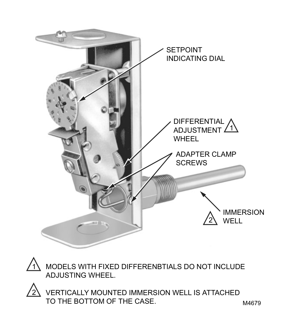
Internal view of the L4006A,B Aquastat controller with the case open, showing the setpoint indicating dial, differential adjustment wheel, adapter clamp screws and horizontal immersion well
Fig. 1. Internal view of L4006A,B with horizontal well. L4006E is the same with reset button added.

Application

Model Switch action How it is used
L4006A Breaks the circuit on a temperature rise to the control setting. High limit or low limit control. When used as a controller or as a low limit, a separate high limit must be used.
L4006B Makes the circuit on a temperature rise. Circulator controller, delaying circulator operation when boiler water temperature is below the control setting.
L4006E Breaks the control circuit when the controlled medium reaches the high limit setting; trip-free manual reset. A reset button on the front of the case must be pressed to re-establish the control circuit.
L4006H Breaks the control circuit at the high limit setting; trip-free manual reset, as on the L4006E. Includes bracket and clamp for surface mounting on pipe or tank.

A plastic bag of heat-conductive compound is included with the L4006A,B,E Aquastat® Controllers for use when the sensing bulb is inserted into a well designed for a large bulb than the one used on the L4006A,B,E. A 124904 Well Adapter, for use on old wells that do not fit the L4006A,B,E immersion well clamp, can be ordered; see form 68-0040, Wells and Fittings for Temperature Controllers. A setting stop is included to prevent setting above a desired temperature on limit.

If a well adapter or other accessories are needed, refer to form 68-0040, Wells and Fittings for Temperature Controllers, for part numbers and ordering information.

Installation

WARNING — Electrical shock hazard. Can cause serious injury, death or equipment damage. Disconnect the power supply before beginning installation to prevent electrical shock or equipment damage.

When installing this product…

  1. Read these instructions carefully. Failure to follow them could damage the product or cause a hazardous condition.
  2. Check the ratings given in the instructions and on the product to make sure the product is suitable for your application.
  3. Installer must be a trained, experienced service technician.
  4. After installation is complete, check out product operation as provided in these instructions.

Installing immersion well models (L4006A,B,E)

Important: Obtain the best thermal response with a well that snugly fits the sensing bulb. The bulb should be inserted until it rests against the bottom of the well. Use a well of correct length and bend the tubing, if necessary, to provide enough force to hold the bulb against the bottom of the well. Do not make a sharp bend in the tubing. A sharp bend can produce a break in the tubing and cause a loss of fill. This condition will cause the high and low limit controls to be made continuously.

If the well is not a snug fit on the bulb, use the heat-conductive compound as follows. Fold the plastic bag of compound lengthwise and twist gently. Snip the end of the bag and insert into the well. Slowly pull out the bag while squeezing firmly to distribute the compound evenly in the well. Insert the bulb into the well. Bend the tubing, if necessary, to provide force to hold the bulb against the bottom of the well and to hold the out end of the bulb in firm contact with the side of the well. Wipe off any excess compound.

Note: Some models have an adjustable capillary tubing length to 3 inches (76 mm). In these models, pull out extra tubing from inside the case, if needed.

Follow the boiler manufacturer instructions, if available; otherwise, proceed as follows.

  1. Remove the old control.
  2. Refer to the cover insert of the old control to identify and tag each lead as it is disconnected.
  3. Leave the old well in place if it is suitable.

If the well is otherwise suitable but does not fit the L4006 immersion well clamp

Use a 124904 Well Adapter (order separately, see form 68-0040) to secure the L4006 to the old well. The adapter has a flange at one end for fastening the L4066 adapter clamp.

  1. Loosen, but do not remove, the two adapter clamp screws (see Fig. 1).
  2. Slide the adapter onto the capillary and short tube; see Fig. 2 inset.
  3. Make sure the flanged end of the adapter fits into the hole in the case. Position the adapter well clamp snugly over the flange on the adapter, then tighten the clamp screws.
  4. Insert the bulb into the well, as shown in Fig. 2. If necessary, use the heat-conductive compound as instructed in the IMPORTANT statement above.
  5. Tighten the setscrew (if one is present in the old well spud) against the adapter.

If the old well is unsuitable

  1. Drain the system and remove the well.
  2. Select a new well from form 68-0040 (order well separately).
  3. Install the new well, refill the system and check for leaks.
  4. Loosen, but do not remove, the two adapter clamp screws (Fig. 1).
  5. Insert the sensing bulb into the well until it bottoms as show in Fig. 2. Add heat-conductive compound, if necessary, as instructed in the IMPORTANT statement above.
  6. Make sure the end of the well fits into the hole in the case. Position the immersion well clamp snugly over the well flange and tighten the clamp screw securely.
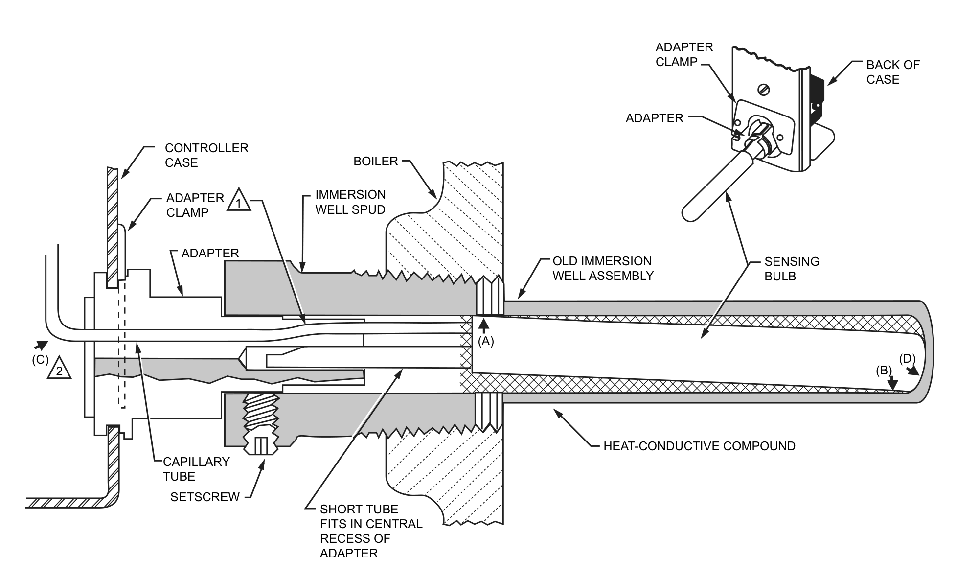
Sectional drawing of the sensing bulb inside an immersion well, showing the well adapter, adapter clamp, capillary tube, setscrew and heat-conductive compound, with an inset of the back of the case
Fig. 2. Bulb in immersion well and use of adapter.
Diagram notes (text version)
  • Slightly bend in tubes should hold bulb in good thermal contact with the well at two opposite points, as in (A) and (B).
  • Assure that tubes fit freely in adapter so that tension of the capillary tube at point (C) holds the sensing bulb in good thermal contact with the bottom of well at point (D).

Surface mounting the L4006H

The L4006H is designed for surface mounting on piping or tank and can be mounted in any position.

When mounting the L4006H on piping, the pipe should be 1 in. (25 mm) diameter or larger for accurate temperature sensing.

  1. Remove any insulation from the pipe.
  2. Thoroughly scrape off all scale, rust or paint.
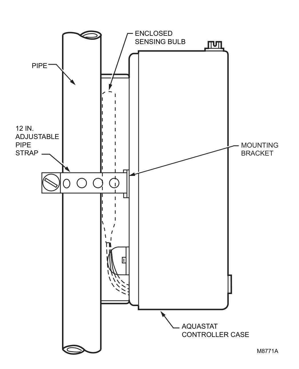
  3. Mount controller as shown in Fig. 3 using adjustable 12 in. (294 mm) pipe strap furnished.

When mounting the L4006H on a tank, use a pipe strap of appropriate length, approximately 6-10 ft (17.6- 29.4m) for the tank (not provided). Fit the pipe strap through the slot in the mounting bracket. See Fig. 3.

L4006H controller case fastened to a vertical pipe with the 12 inch adjustable pipe strap and mounting bracket
Fig. 3. Mount L4006H directly on surface.

Wiring

WARNING — Electrical shock hazard. Can cause serious injury, death or equipment damage. Disconnect power supply before connecting wiring to avoid electrical shock or equipment damage.

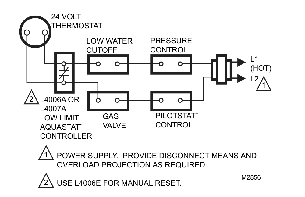
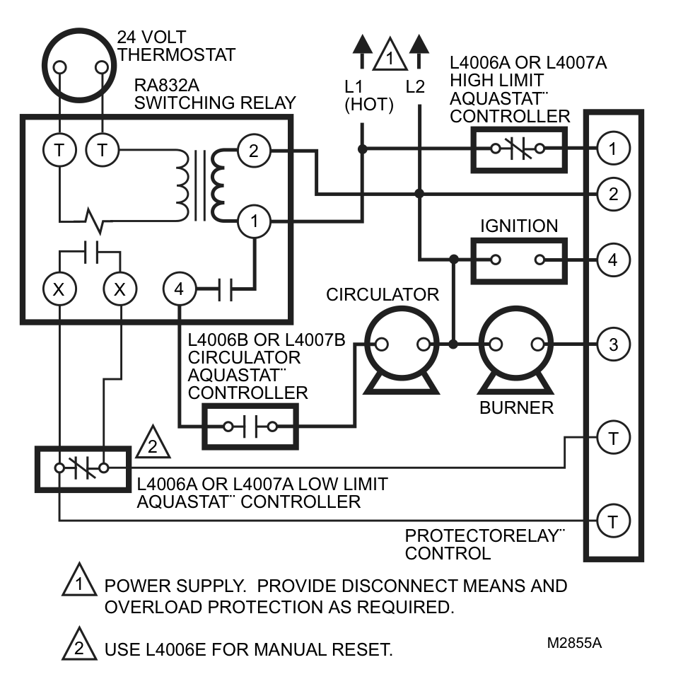
All wiring must comply with local codes and ordinances regarding wire size, insulation, enclosure, etc. See Fig. 4 and 5 for typical diagrams of Aquastat® Controllers used in heating systems.

Use these Aquastat Controllers with copper wire only.

Typical hookup diagram for a gas-fired system with domestic hot water: 24 volt thermostat, low water cutoff, pressure control, L4006A or L4007A low limit Aquastat controller, gas valve and Pilotstat control
Fig. 4. Typical hookup for gas-fired system with domestic hot water.
Diagram notes (text version)
  • Power supply. Provide disconnect means and overload projection as required.
  • Use L4006E for manual reset.
Hookup diagram for an oil-fired summer-winter hydronic system with domestic hot water: RA832A switching relay, high limit and low limit Aquastat controllers, circulator Aquastat controller, ignition, circulator, burner and Protectorelay control
Fig. 5. Hookup for oil-fired, summer-winter, hydronic system with domestic hot water. This is typical where control for domestic hot water is added, or where each Aquastat Controller is mounted in a separate location.
Diagram notes (text version)
  • Power supply. Provide disconnect means and overload protection as required.
  • Use L4006E for manual reset.

Operation

For proper selections of settings, follow boiler manufacturer recommendations:

  1. High limit controller: Shuts off burner when water temperature exceeds high limit setting. Burner restarts when temperature drops to high limit setting minus the temperature differential.

Note: If L4006E or H, see Manual Reset section.

  1. Low limit controller: Maintains minimum boiler temperature for domestic hot water. Turns boiler on at temperature setting, less differential.
  2. Circulator controller: Prevents circulation of water that is not hot enough. Breaks circulator circuit at temperature setting minus differential and remakes at setting.

Adjustment

Set the differential to correspond with the boiler manufacturer recommendations. To adjust models with adjustable differential, rotate the wheel on the back of the snap switch until the desired reading is aligned with the V notch in the frame. The wheel provides an adjustment from 5°F to 30°F (3°C to 17°C). Replace the cover on the Aquastat Controller.

Adjust the control point to correspond with the boiler manufacturer recommendations. To adjust, insert a screwdriver in the slotted screw type head located beneath the window in the cover. Turn the scale to the desired control point.

Manual reset

When the device includes manual reset (L4006E and H), be sure to press the red reset button on the front of the case to make sure that the controller is not locked out on safety. When checking out the system, adjust the control point low enough so the temperature of the controlled medium reaches the high limit setting, the burner shuts off, and the Aquastat Controller locks out. When the temperature of the controlled medium drops to the high limit setting minus differential, push the manual reset button and the system should be operative again. Reset control to proper high limit setting.

Checkout

Check to make certain that the Aquastat Controller has been installed and adjusted properly. Put the system into operation and observe the action of the device through several cycles to make certain that it provides proper control of the system as described in the Operations section. Further adjustments can be made to meet more exact comfort requirements.

Heat-conductive compound: material safety data sheet (DS9021)

Section 1. Product and company identification

  • Product name: Heat Conductive Compound
  • MSDS ID: DS9021
  • Synonyms: MS1699
  • Product use: Heat conductive material used to enhance contact and heat transfer in temperature sensor applications.
  • Manufacturer: Resideo Technologies Inc., 1985 Douglas Drive North, Minneapolis, MN 55422.
  • Date released: October 8, 1999
  • Customer Response Center: 800-328-5111
  • Emergency telephone information: 888-809-3787
  • NFPA ratings: Health 0; Flammability 1; Reactivity 0; Personal Protection B

Section 2. Composition, information on ingredients

Ingredient CAS number Percent PEL TVL
#2 Lithium Complex Grease (70%):
Mineral Oil 64742-65-0 35-50 5 mg/m3 5 mg/m3
Mineral Oil 64742-62-7 20-25 5 mg/m3 5 mg/m3
Lithium Hydrostearate/Sebacate Complex 68815-49-6 4-9 — —
Zinc Alkyldithiophosphate 68649-42-3 0-2 — —
Aluminum Paste (30%):
Aluminum, as Al 7429-90-5 20-25 15 mg/m3 10 mg/m3
Aliphatic Petroleum Distillates 8052-41-3 10-15 2900 mg/m3 525 mg/m3
Stearic Acid 57-11-4 1-2 — —
Aromatic Petroleum Distillates 64742-95-6 1-2 5 mg/m3 5 mg/m3

Additional information: Part No. 120650 (0.5 oz tube); Part No. 107408 (4 oz can); Part No. 197007 (5 gallon container). May also contain minute amounts of lithium and molybdenum lubricant compounds.

Section 3. Hazard identification

Acute health effects

  • Skin: Excessive contact may cause skin irritation and dermatitis.
  • Eye: Direct contact with eye will cause irritation.
  • Inhalation: No adverse effects are expected.
  • Ingestion: Ingestion of product may cause nausea, vomiting and diarrhea.

Chronic health effects

  • Existing skin rash or dermatitis may be aggravated by repeated contact.
  • OSHA hazard classifications: None.
  • Carcinogenicity: Not considered to be a carcinogen by either OSHA, NTP, IARC, or ACGIH.

Section 4. First aid measures

  • Eye contact: Flush eyes with water for 15 minutes. Remove any contact lenses and continue to flush. Obtain medical attention if irritation develops and persists.
  • Skin contact: Remove excess with cloth or paper. Wash thoroughly with mild soap and water. Obtain medical attention if irritation develops and persists.
  • Ingestion: Contact physician or local poison control center immediately.
  • Inhalation: Remove patient to fresh air and obtain medical attention if symptoms develop.

Section 5. Fire fighting measures

  • Material flash point: > 383°F (195°C). Will burn if exposed to flame.
  • Extinguishing media: Carbon dioxide, dry chemical or foam.
  • Special fire fighting procedures: None.
  • Explosion hazards: None. Aluminum powder can react with water to release flammable hydrogen gas. In the form of this product, this reaction is not expected.

Section 6. Accidental release measures

Scrape up and dispose of as solid waste in accordance with state and federal regulations.

Section 7. Handling and storage

Store in dry place. Keep container closed when not in use.

Section 8. Exposure controls and personal protection

  • Ventilation: No special ventilation is required when working with this product.
  • Respiratory protection: None required.
  • Eye protection: Not normally required. However, use chemical safety goggles or faceshield if potential for eye contact exists, especially if material is heated.
  • Hand/clothing protection: Not normally required. Protective gloves and clothing are recommended, as material is difficult to remove from skin and clothing.
  • Other protective equipment: None required.

Section 9. Physical and chemical properties

  • Appearance/odor: Aluminum color, semi-solid material, pleasant odor.
  • Solubility in water: Negligible.
  • Specific gravity: 0.86.

Section 10. Stability and reactivity

  • Stability: Stable.
  • Reactivity: Hazardous polymerization will not occur.
  • Incompatibilities: Strong oxidizing agents and halogens.
  • Hazardous decomposition products: Carbon dioxide, carbon monoxide.

Section 11. Toxicology information

No data available.

Section 12. Ecological information

Chemical fate information: Hydrocarbon components will biodegrade in soil; relatively persistent in water.

Section 13. Disposal consideration

Dispose of as solid waste in accordance with local, state and federal regulations.

Section 14. Transportation information

DOT classification: Not classified as hazardous.

Section 15. Regulatory information

SARA Title III supplier notification: Include in Section 311/312 inventory reports if amounts exceed 10,000 pounds. Aluminum compounds are subject to the reporting requirements under Section 313 of Emergency Planning and Community Right-To-Know Act of 1986 (40 CFR 372). Ingredients listed in TSCA Inventory.

Section 16. Other information

This information is furnished without warranty, expressed or implied, except that is is accurate to the best of our knowledge.

Document information

Resideo Technologies, Inc., 1985 Douglas Drive North, Golden Valley, MN 55422. Customer care: 1-800-468-1502. www.resideo.com. © 2020 Resideo Technologies, Inc. All rights reserved. This product is manufactured by Resideo Technologies, Inc. and its affiliates.

60-0915—06   M.S. Rev. 05-20  |  Printed in United States

Download:Honeywell L4006,7,8; L6006,7,8 AquastatÆ Controllers Manual.pdf

Honeywell CT410B Thermostats Installation Instructions

above.

Resideo T410 line voltage electric heat thermostat with temperature setting knob
T410 electric heat thermostat.

Specifications

  • Models: T410A provides single-line break. T410B provides double-line break.
  • Temperature range: 40°F to 80°F (4°C to 27°C)
  • Electrical ratings: 60 Hz noninductive; 22A at 120-240 Vac; 19A at 277 Vac

Safety notices

WARNING — Electric shock hazard. This thermostat is a line voltage control (120 Volts to 277 Volts.) Do not install it if you are not completely familiar with house wiring. If handled improperly, there can be risk of a 120 Volt to 277 Volt electric shock hazard, which may cause serious injury or death.

Mercury notice. If this control is replacing a control that contains mercury in a sealed tube, do not place you old control in the trash. Dispose of properly.

Contact you local waste management authority for instruction regarding recycling and the proper disposal of a old control.

1. Preparation

  1. Proper installation of your Resideo thermostat will occur if you follow these instructions STEP-BY-STEP. It is recommended that as you read, understand and complete each step, you check it off with pencil or pen.
  2. Check thermostat suitability for your home system by reviewing the ratings listed on this page.
  3. Make certain that your heating system is working, especially if it has been inoperative for a length of time. If the system does not work, contact your local electrician for assistance.
  4. Carefully unpack your new thermostat. To avoid damage to the sensing element, do NOT remove the thermostat cover until wiring has been completed.
  5. Save packages of screws, instructions, receipt and proof-of-purchase.

2. Remove Old Thermostat

WARNING — Electric shock hazard. Begin by turning off power to the heating circuit at the main service panel.

  1. Remove cover of old thermostat. Cover normally snaps off when pulled firmly from the bottom. If it resists, check for a screw that locks the cover.
  2. Loosen screws holding thermostat base to outlet box and lift away.
  3. Disconnect wires from old thermostat. As you disconnect each wire, tape the end and label it with the letter of the terminal designation to make reconnection to new thermostat easier.
  4. Check the old insulation for cracks, nicks or fraying, and apply high quality plastic tape where necessary for adequate insulation.
  5. Retain the old thermostat for reference purposes and until your new thermostat is functioning smoothly.

3. Wire and Mount New Thermostat

  1. Connect wires to the thermostat as shown in the applicable wiring diagram.
  2. Remove thermostat cover by grasping the top and bottom ends with fingers, and pulling outward.
  3. Push the wires into the outlet box, and insert the thermostat into the box for mounting by pushing against top and bottom of the thermostat base.

Important: Do not press on setting knob.

  1. Secure the thermostat to the box with the two captive mounting screws provided.
  2. Replace thermostat cover.
  3. Set knob to desired room temperature.

Important: Rough handling or strong pressure can damage knob or sensing element, and change calibration.

Wiring diagrams for T410B double-line break and T410A single-line break thermostats, with legend notes and caution about aluminum conductors
Fig. 1. T410B (double-line break, left) and T410A (single-line break, right) wiring diagrams.
Diagram notes (text version)
  • Power supply. Provide disconnect means and overload protection as required.
  • Breaks on positive off.
  • Exposed unused leadwires to be properly insulated.
  • Thermally activated—breaks on temperature rise. Makes on temperature fall.

Caution: Special service CO/ALR solderless connectors must be used when connecting with aluminum conductors; otherwise, a fire hazard can result.

4. Check Out Thermostat

  1. Turn on the power to the heating system.
  2. Turn setting knob all the way clockwise; listen for clicking sound as switch makes contact. Electric heater should begin operation.
  3. Turn knob all the way counterclockwise; listen for clicking sound as switch breaks contact. Electric heater should shut off.

5. Setting Thermostat

  1. Begin with knob to the desired setting (typically 70°F [20°C] on the scale).
  2. If this setting is not satisfactory after at least two hours of operation, turn setting knob upscale to raise the temperature, or downscale to lower the temperature. Move knob only a degree each time.

6. Troubleshooting

Your Resideo thermostat requires little or no attention. Most problems can generally be traced to the following:

Table 1. Troubleshooting.

Symptom Checkout Action
No heat. Make sure power is on at main service panel. Turn the temperature setting knob fully clockwise. Heater should start to warm up within two minutes. If not, contact qualified electrician to check thermostat and heater.
Improper connections to thermostat. With power to circuit OFF, tighten all wiring connections. Repair any frayed or broken wires.
Other. Contact a qualified electrician for assistance.
Heater never turns off. Turn temperature setting knob fully counterclockwise. Heater should start to cool within minutes. If not, turn off power at the main service panel, and contact qualified electrician.
Thermostat setting and thermometer reading disagree. Thermostat affected by drafts or radiant heat. Contact electrician to change the location. The thermostat should be about 5 ft (1.5m) above the floor and on an inside wall.

1-Year Limited Warranty

Resideo warrants this product, excluding battery, to be free from defects in workmanship or materials, under normal use and service, for a period of one (1) years from the date of first purchase by the original purchaser. If at any time during the warranty period the product is determined to be defective due to workmanship or materials, Resideo shall repair or replace it (at Resideo’s option).

If the product is defective,

  1. return it, with a bill of sale or other dated proof of purchase, to the place from which you purchased it; or
  2. call Resideo Customer Care at 1-800-468-1502. Customer Care will make the determination whether the product should be returned to the following address: Resideo Return Goods, 1985 Douglas Dr. N., Golden Valley, MN 55422, or whether a replacement product can be sent to you.

This warranty does not cover removal or reinstallation costs. This warranty shall not apply if it is shown by Resideo that the defect was caused by damage which occurred while the product was in the possession of a consumer.

Resideo’s sole responsibility shall be to repair or replace the product within the terms stated above. RESIDEO SHALL NOT BE LIABLE FOR ANY LOSS OR DAMAGE OF ANY KIND, INCLUDING ANY INCIDENTAL OR CONSEQUENTIAL DAMAGES RESULTING, DIRECTLY OR INDIRECTLY, FROM ANY BREACH OF ANY WARRANTY, EXPRESS OR IMPLIED, OR ANY OTHER FAILURE OF THIS PRODUCT.

Some states do not allow the exclusion or limitation of incidental or consequential damages, so this limitation may not apply to you.

THIS WARRANTY IS THE ONLY EXPRESS WARRANTY RESIDEO MAKES ON THIS PRODUCT. THE DURATION OF ANY IMPLIED WARRANTIES, INCLUDING THE WARRANTIES OF MERCHANTABILITY AND FITNESS FOR A PARTICULAR PURPOSE, IS HEREBY LIMITED TO THE ONE YEAR DURATION OF THIS WARRANTY. Some states do not allow limitations on how long an implied warranty lasts, so the above limitation may not apply to you.

This warranty gives you specific legal rights, and you may have other rights which vary from state to state. If you have any questions concerning this warranty, please write Resideo Customer Care, 1985 Douglas Dr, Golden Valley, MN 55422 or call 1-800-468-1502.

Document information

This product is manufactured by Resideo Technologies, Inc., Golden Valley, MN, 1-800-468-1502. ©2019 Resideo Technologies, Inc. The Honeywell Home trademark is used under license from Honeywell International Inc. All rights reserved. www.resideo.com

Resideo Inc., 1985 Douglas Drive North, Golden Valley, MN 55422

69-1562—02   M.S. Rev. 07-19  |  Printed in United States