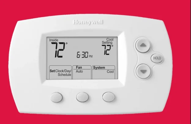
The TH6220D goes on the wall of a system that can have two stages of heat and two of cooling, and the booklet assumes the person holding the screwdriver has done this before. It opens with a line that is easy to skip: the thermostat must be installed by a trained, experienced technician. What follows is what that technician needs, from the wall anchors to the fifteen installer functions and the thirteen faults the booklet prints. The document is 69-1785, dated 01-2005, and the pages here follow its own three-part order.
Download Honeywell FocusPRO TH6220D Installation Manual (PDF)
Table of Contents
Installation
What the TH6220D Controls
Printed page 1 states the application in one sentence: electronic control of 24 VAC single-stage and multi-stage heating and cooling systems, or 750 mV heating systems. The system types it covers run up to 2 heat and 2 cool, and the list on that page is six items long:
- Gas, oil, or electric heat with air conditioning
- Warm air, hot water, high-efficiency furnaces, heat pumps, steam, gravity
- Heat only, in two-wire systems, in systems that power open and close zone valves (Series 20), and in normally-open zone valves
- Heat only with fan
- Cool only
- 750 mV heating systems
Power comes three ways: battery only, common wire only, or common wire with battery backup. Changeover is selectable, manual or auto. The system switch carries Heat, Off, Cool, Auto and Em Heat, and the fan switch carries Auto and On.
The same page carries the installer warning in a shaded box, with three lines under it. Read the instructions carefully, because failing to follow them can damage the product or cause a hazardous condition. Check the ratings on page 17 to confirm the product suits the application. Always test for proper operation after installation, which is the procedure on page 13. Two notices follow the box: an electrical hazard caution requiring the power to be disconnected before installation begins, and a mercury notice for anyone replacing a control that contains mercury in a sealed tube.
Before You Open the Wall
The package holds five items, drawn as pictures on printed page 2: the TH6220D thermostat with the wallplate attached to the back, a quick reference card, the operating manual, wall anchors and mounting screws at two of each, and two AA alkaline batteries.
The tool list on the same page is eight lines: a No. 2 Phillips screwdriver, a small pocket screwdriver, a drill, a drill bit, a hammer, a pencil, electrical tape and, marked optional, a level. The drill bit line gives both sizes in one entry: 3/16 in for drywall and 7/32 in for plaster. Those are the only two hole sizes the booklet prints, and they appear again on the wallplate drawing on page 3.
Placement is on the right half of page 1, under the heading Installation tips. The thermostat goes about 5 feet (1.5 m) above the floor, in an area with good air circulation at average temperature. The drawing marks three positions with an X and the word NO, and the list beneath names five conditions to avoid: drafts or dead spots behind doors and in corners, hot or cold air from ducts, sunlight or radiant heat from appliances, concealed pipes or chimneys, and unheated or uncooled areas such as an outside wall behind the thermostat.
Mounting the Wallplate
The wallplate comes off the thermostat before anything else. The instruction is to put a finger into the wire hole and pull, and the drawing shows the plate separating from the body with the quick reference card slot visible on its back.
Five numbered steps follow on printed page 3:
- Insert the quick reference card in the slot in the back of the thermostat.
- Pull the wires through the wire hole.
- Position the wallplate on the wall, level it, and mark the hole positions with a pencil.
- Drill the holes at the marked positions, then tap in the supplied wall anchors.
- Place the wallplate over the anchors, insert the mounting screws and tighten them.
The drawing under the steps labels the wire hole, the wall anchors and the mounting screws, and repeats the two drill sizes.
Wiring
Printed page 4 gives three instructions. Loosen the screw terminals, insert the wires into the terminal block, then re-tighten the screws. Push the excess wire back into the wall opening, keeping it inside the shaded area the drawing marks. Plug the wall opening with non-flammable insulation so drafts cannot affect thermostat operation. The wire specification is 18- to 22-gauge thermostat wire, and shielded cable is not required.
Four notes sit under the drawing on the same page, and each one decides a wiring question that comes up on the wall.
| Note | What the page says |
|---|---|
| R and Rc terminals | In a single-transformer system, leave the metal jumper in place between R and Rc. Remove it if the system has two transformers. |
| C terminal | The common wire terminal is optional when the thermostat is powered by batteries. |
| W (O/B) terminal | If the thermostat is configured for a heat pump in the installer setup, configure the changeover valve for cool, which is the O setting the unit ships in, or for heat, which is B. |
| L terminal (output) | Heat pump reset. The L terminal is powered continuously when the thermostat is set to Em Heat. Configure the thermostat for 2 heat / 1 cool heat pump in the installer setup. |
The Two Terminal Designation Lists
The drawing on page 4 prints two rows of terminals on one block. The upper row is the conventional set, in this order: Y2, W2, G, W, C, Y, R, Rc. The lower row is the heat pump set: L, E, Aux, G, O/B, C, Y, R, Rc. The page gives a definition for every letter, and the two lists are not the same length.
| Conventional terminal | Function as printed |
|---|---|
| Y2 | 2nd stage compressor contactor |
| W2 | 2nd stage heat relay |
| G | Fan relay |
| W | 1st stage heat relay |
| C | Common wire from secondary side of cooling system transformer |
| Y | 1st stage compressor contactor |
| R | Heating power. Connect to secondary side of heating system transformer. |
| Rc | Cooling power. Connect to secondary side of cooling system transformer. |
| Heat pump terminal | Function as printed |
|---|---|
| L | Heat pump reset. L terminal powered continuously when System is set to Em Heat. |
| E | Emergency heat relay |
| Aux | Auxiliary heat relay |
| G | Fan relay |
| O/B | Changeover valve for heat pumps |
| C | Common wire from secondary side of cooling system transformer |
| Y | Compressor contactor |
| R | Heating power. Connect to secondary side of heating system transformer. |
| Rc | Cooling power. Connect to secondary side of cooling system transformer. |
The Ten Wiring Diagrams
Pages 5 to 9 carry ten diagrams, two per page. Each page repeats the same nine-item key before the drawings, and several of its entries tell you what to set in the installer setup rather than what to connect. The diagrams, in page order:
| Printed page | Diagram |
|---|---|
| 5 | Typical 1H/1C system, 1 transformer |
| 5 | Typical 1H/1C system, 2 transformers |
| 6 | Typical 1H/1C heat pump system |
| 6 | Typical heat-only system |
| 7 | Typical heat-only system with fan |
| 7 | Heat-only system (Series 20) |
| 8 | Typical cool-only system |
| 8 | Heat-only system (normally open zone valve) |
| 9 | Typical 2H/2C system (1 transformer) |
| 9 | Typical 2H/1C heat pump system |
The key that sits above them carries nine items. Power supply, with disconnect means and overload protection as required. Pre-installed jumper, removed for 2-transformer systems only. Optional 24 VAC common connection. Then five instructions that name a setting rather than a wire: set the system type to Heat Only; set it to 1 Heat/1 Cool Heat Pump and set the changeover valve to O or B; set it to 2 Heat/1 Cool Heat Pump; set it to 2 Heat/2 Cool conventional; and install a field jumper between Aux and E if there is no emergency heat relay. The ninth item states that the L terminal is powered continuously when the thermostat is set to Em Heat.
The 2-transformer drawing is the one that shows the jumper coming out. It marks the jumper with an arrow and the words Remove jumper, which is the same rule the R and Rc note on page 4 gives in words.
Power Options and Hanging the Thermostat
Printed page 10 splits power into two halves. For AC power, the thermostat runs from 24 VAC, and the common side of the cooling transformer connects to the C terminal as the drawing shows. The page adds an important line in bold: remove the R/Rc jumper for 2-transformer systems only, and points to the wiring diagram on page 5. For battery power, the thermostat can run on batteries alone, or on AC power with the batteries as backup. During power interruptions the batteries save the time and day settings and power the display. Once the unit is up, the batteries can be changed without removing the thermostat from the wall, which is the procedure on page 15.
Mounting the body takes one step. Align the four tabs on the wallplate with the corresponding slots on the back of the thermostat, then push gently until it snaps in place. The drawing shows the four tabs, the battery compartment and the connector block that meets the pins on the back of the body.
Setup and Testing
Opening the Installer Setup
The installer setup on page 11 configures the thermostat to match the installed heating and cooling system. It is opened by pressing and holding the up arrow and the FAN button together until the display changes. Inside the menu, the up or down arrow changes the setting, NEXT advances to the next function, and DONE exits and saves. The display shows the function number on the left and the setting on the right, which is the pair the table below is written in.
Fifteen functions are printed, and the numbering is not continuous. Functions 1, 2, 3, 5, 6, 8, 9, 10, 12, 13, 14, 15, 16, 27 and 28 appear across pages 11 and 12. Numbers 4, 7 and 11, and everything from 17 to 26, are not printed in this booklet.
Functions 1 to 3: What the Thermostat Is Attached To
| Function | Name | Options as printed |
|---|---|---|
| 1 | System type | 0 Gas, oil or electric heat with air conditioning; 1 1 heat/1 cool heat pump; 2 Heat only (2-wire systems / power to open and close zone valves / normally open zone valves); 3 Heat only with fan; 4 Cool only; 5 2 heat/1 cool heat pump; 6 2 heat/2 cool conventional; 7 2 heat/1 cool conventional; 8 1 heat/2 cool conventional |
| 2 | Changeover valve (O/B terminal) | 0 Changeover valve (O/B terminal energized in cooling); 1 Changeover valve (O/B terminal energized in heating) |
| 3 | Fan control (heating) | 0 Gas or oil furnace, equipment controls fan in heating; 1 Electric furnace, thermostat controls fan in heating |
Function 1 is the one the troubleshooting table sends you back to most often. Four of the thirteen entries point at it, which makes the system type the first thing to confirm when a system behaves as though it is wired for something else.
Functions 5 to 10: Cycle Rates
| Function | Name | Options as printed |
|---|---|---|
| 5 | Heat cycle rate (CPH: cycles/hour) | 5 For gas or oil furnaces of less than 90% efficiency; 1 For steam or gravity systems; 3 For hot water systems and furnaces of over 90% efficiency; 9 For electric furnaces. Other options: 2, 4, 6, 7, 8, 10, 11 or 12 CPH |
| 6 | Second stage heat cycle rate / auxiliary heat (CPH) | Same four settings and the same other options as function 5 |
| 8 | Emergency heat cycle rate (CPH) | 9 For electric emergency heat; 1 For steam or gravity systems; 3 For hot water systems and furnaces of over 90% efficiency; 5 For gas or oil furnaces of less than 90% efficiency. Other options: 2, 4, 6, 7, 8, 10, 11 or 12 CPH |
| 9 | Compressor cycle rate (CPH) | 3 Recommended for most compressors. Other options: 1, 2, 4, 5 or 6 CPH |
| 10 | Second stage compressor cycle rate (CPH) | 3 Recommended for most compressors. Other options: 1, 2, 4, 5 or 6 CPH |
Functions 12 to 28: Behaviour, Display and Limits
| Function | Name | Options as printed |
|---|---|---|
| 12 | System setting adjustment | 0 Manual changeover (Heat/Cool/Off); 1 Auto changeover (Heat/Cool/Auto/Off); 2 Auto changeover only (Auto) |
| 13 | Adaptive Intelligent Recovery | 1 On; 0 Off |
| 14 | Temperature display | 0 Fahrenheit; 1 Celsius |
| 15 | Compressor protection | 5 Five-minute compressor off time. Other options: 0, 1, 2, 3 or 4-minute off time |
| 16 | Schedule format | 0 5/2 (programmable weekdays and weekends); 1 5/1/1 (weekdays, Saturday and Sunday programmable) |
| 27 | Heat temperature range stops | 90 Highest heating temperature setting; 40-89 Heating temperature range, in increments of 1°F or 0.5°C |
| 28 | Cool temperature range stops | 50 Lowest cooling temperature setting; 51-99 Cooling temperature range, in increments of 1°F or 0.5°C |
The Installer System Test
Page 13 runs the equipment through a test sequence, and it is opened differently from the installer setup: press and hold the up arrow and the down arrow together until the display changes. The up arrow turns the system on, the down arrow turns it off, NEXT advances to the next test, and DONE terminates the test.
A caution sits beside the table. Compressor protection, the minimum off time, is bypassed during testing, and cycling the compressor quickly can damage it.
| Test | System | Status values |
|---|---|---|
| 10 | Heating system | 0 Heat and fan turn off; 1 Heat turns on, and the fan also turns on immediately if function 1 is set to 1 or 5, or if function 3 is set to 1; 2 Second stage heat turns on |
| 20 | Emergency heating system | 0 Heat and fan turn off; 1 Heat and fan turn on; 2 Second stage heat turns on (Aux) |
| 30 | Cooling system | 0 Compressor and fan turn off; 1 Compressor and fan turn on; 2 Second stage compressor turns on |
| 40 | Fan system | 0 Fan turns off; 1 Fan turns on |
| 70 | Thermostat information, for reference only | 71 Software revision number (major); 72 Software revision number (minor); 73 Configuration identification code (major); 74 Configuration identification code (minor); 75 Production configuration date code (week); 76 Production configuration date code (year) |
The Three Features Page 14 Explains
The table of contents calls page 14 Explanation of features, and the page carries three headings, each naming the setup function that controls it.
Auto Changeover (function 12) is for climates where both air conditioning and heating are used on the same day. When the system is set to Auto, the thermostat selects heating or cooling depending on the indoor temperature. The heat and cool settings must be at least 3 degrees apart, and the thermostat adjusts the settings to keep that 3-degree separation, which it calls the deadband. The page states that the separation is fixed and cannot be changed.
Adaptive Intelligent Recovery (function 13) lets the thermostat learn how long the furnace and air conditioner take to reach the temperature you want. The schedule is set to the time the house should reach the temperature, and the thermostat starts heating or cooling early enough to arrive there on time. The page gives one example: with the Wake time at 6 am and the temperature at 70°, the heat comes on before 6 am so the house is at 70° by the time you wake.
Built-in compressor protection (function 15) prevents damage to the compressor in an air conditioning or heat pump system, which can happen if the compressor restarts too soon after a shutdown. The feature forces the compressor to wait for a few minutes before restarting. While it waits, Cool On, or Heat On on heat pumps only, flashes on the display, and the message stops flashing when the safe wait time has elapsed. Function 15 itself prints the wait as five minutes, with 0 to 4 minutes available as other options.
Appendices
Quick Reference to Controls
Page 15 names the hardware. The digital display screen fills most of the front. The battery holder sits behind the body and is referred to page 10 for the mounting context. The two temperature buttons adjust temperature settings. The Hold button overrides programmed temperature control. The three function buttons select whatever function is displayed just above them, and those labels change with the task.
Quick Reference to the Display
The same page labels the screen. The current inside temperature is the large figure, with the temperature setting beside it. The low battery warning reads Replace Battery. The current time and day sit above the schedule controls. The current program period shows one of Wake, Leave, Return or Sleep. In Recovery appears when Adaptive Intelligent Recovery has started the equipment ahead of schedule. Auxiliary heat appears only on heat pumps with auxiliary heat. System status shows Heat On or Cool On, and a flashing message sends you to page 14. The system setting line carries Heat, Cool, Auto, Off and Em Heat, and the fan line carries Auto and On. The Set Clock/Day/Schedule button sets the time, the day or the program schedules.
Battery Replacement
The batteries change without taking the thermostat off the wall. Press and pull to remove the holder, insert fresh AA alkaline batteries, then reinstall the holder. The drawing shows the holder coming out of the top of the body and the two cells in their orientation.
In Case of Difficulty
The troubleshooting table on pages 16 and 17 is printed in two columns, seven entries in the left column and six in the right. The order below follows the page, left column first. Every symptom is printed as the table prints it.
| Symptom | What the table says to do |
|---|---|
| Display is blank | Check the circuit breaker and reset if necessary. Make sure the power switch at the heating and cooling system is on. Make sure the furnace door is closed securely. If the thermostat is battery powered, make sure fresh AA alkaline batteries are correctly installed, page 10. |
| Temperature settings do not change | Make sure the heating and cooling temperatures are set to acceptable ranges: Heat 40° to 90°F (4.5° to 32°C), Cool 50° to 99°F (10° to 37°C). Check the temperature range stop settings, functions 27 and 28 on page 12. |
| Heating system does not respond (“Heat On” appears on screen) | Check for 24 Vac at the equipment on the secondary side of the transformer between power and common. If voltage is not present, check the heating equipment to find the cause. Check for 24 Vac between the heat terminal (W) and the transformer common; if 24 Vac is present, the thermostat is functional, so check the heating equipment. Check for loose or broken wires between the thermostat and the heating equipment. |
| Cooling system does not respond (“Cool On” appears on screen) | Check for 24 Vac at the equipment on the secondary side of the transformer between power and common. If voltage is not present, check the cooling equipment to find the cause. Check for 24 Vac between the cooling terminal (Y) and the transformer common; if 24 Vac is present, the thermostat is functional, so check the cooling system. Check for loose or broken wires between the thermostat and the cooling equipment. |
| Fan does not turn on in a call for heat | Check installer setup, function 3 (Fan Control), to make sure the fan control is set to match the type of system, page 11. |
| Heat pump issues cool air in heat mode, or warm air in cool mode | Check installer setup, function 2 (Changeover Valve), to make sure it is configured for the system, page 11. |
| Heat/cool both on at same time, or heat does not turn off | Check installer setup, function 1 (System Type), to make sure it matches the installed equipment, page 11. Check that the heating and cooling wires are not shorted together. |
| Heating equipment is running in cool mode | Check installer setup, function 1 (System Type), to make sure it matches the installed equipment, page 11. |
| Cannot change system setting to “Heat” | Check installer setup, function 1 (System Type), to make sure it matches the installed heating equipment, page 11. Change installer setup, function 12 (System Setting), to Manual or Auto Changeover, page 12. |
| Cannot change system setting to “Cool” | Check installer setup, function 1 (System Type), to make sure it matches the installed cooling equipment, page 11. Change installer setup, function 12 (System Setting), to Manual or Auto Changeover, page 12. |
| “Heat On” is not displayed | Change the system setting to Heat, and set the temperature level above the current room temperature. |
| “Cool On” is not displayed | Change the system setting to Cool, and set the temperature level below the current room temperature. |
| “Cool On” or “Heat On” is flashing | Compressor protection timeout is engaged. Wait 5 minutes for the system to restart safely, without damage to the compressor. |
Accessories and Specifications
Two replacement parts are listed, and the booklet sends you to a distributor to order them. The battery holder is part number 50007072-001. The cover plate assembly is part number 50002883-001, which the page describes as the part that covers marks left by old thermostats.
The specification block on page 17 gives the ranges and the load limits.
| Item | Rating |
|---|---|
| Temperature ranges | Heat 40° to 90°F (4.5° to 32°C); Cool 50° to 99°F (10° to 37°C) |
| Operating ambient temperature | 32° to 120°F (0° to 48.9°C) |
| Shipping temperature | -20° to 120°F (-28.9° to 48.9°C) |
| Operating relative humidity | 5% to 90%, non-condensing |
| Physical dimensions | 3-9/16 in H x 5-13/16 in W x 1-1/2 in D; 91 mm H x 147 mm W x 38 mm D |
| Terminal | Load | Voltage (50/60 Hz) | Running current |
|---|---|---|---|
| W (O/B) | Heating | 20-30 Vac | 0.02-1.0 A |
| W (O/B) | Powerpile | 750 mV DC | 100 mA DC |
| W2 (Aux) | Heating | 20-30 Vac | 0.02-0.5 A |
| Y | Cooling | 20-30 Vac | 0.02-1.0 A |
| Y2 | Cooling | 20-30 Vac | 0.02-1.0 A |
| G | Fan | 20-30 Vac | 0.02-0.5 A |
| E | Emergency heat | 20-30 Vac | 0.02-1.0 A |
| L | Heat pump reset | 20-30 Vac | 0.02-0.5 A |