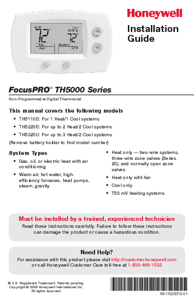
This Honeywell FocusPRO TH5000 Series Installation Manual guide is for the technician with a non-programmable FocusPRO on the bench and a cable of unknown parentage coming out of the wall. Every terminal list, wiring note, setup function and rating below is quoted from the guide, with the page number attached.
It is eight English pages long and assumes you already know what a transformer does. What you get is a model-to-system map, fourteen wiring configurations, twelve numbered notes and an installer setup table. Read it as a lookup sheet, not a tutorial.
Download Honeywell FocusPRO TH5000 Series Installation Manual (PDF)
Table of Contents
Models and System Types
Page 1 labels the product a “Non-Programmable Digital Thermostat” and names its audience: “Must be installed by a trained, experienced technician”. The warning that follows is why you read the pages — “Failure to follow these instructions can damage the product or cause a hazardous condition.”
The footer document id is 69-1922EFS—03, and page 8 carries “© 2020 Resideo Technologies, Inc. All rights reserved.” — the series is sold through Resideo.
“This manual covers the following models”, and the split is by staging capacity rather than features:
- “TH5110D: For 1 Heat/1 Cool systems”
- “TH5220D: For up to 2 Heat/2 Cool systems”
- “TH5320U: For up to 3 Heat/2 Cool systems (Remove battery holder to find model number)”
Shaded areas in the wiring pages “apply only to TH5320U/TH5220D or as otherwise noted”, so the model decides which rows are live. For FocusPRO TH5110D installation the board carries only Rc, Y, W, G, R and C.
Six system types are in scope: “Gas, oil, or electric heat with air conditioning”, “Warm air, hot water, high-efficiency furnaces, heat pumps, steam, gravity”, “Heat only — two-wire systems, three-wire zone valves (Series 20), and normally open zone valves”, then “Heat only with fan”, “Cool only” and “750 mV heating systems”.
Before You Install
Page 2 leads with a “CAUTION: ELECTRICAL HAZARD” that “Can cause electrical shock or equipment damage. Disconnect power before beginning installation.” The mercury notice covers whatever you just removed: “If this product is replacing a control that contains mercury in a sealed tube, do not place the old control in the trash.”
Wallplate work is “Separate wallplate from thermostat.”, then “Mount wallplate as shown below.”, with hole sizes that depend on the wall: “Drill 3/16” holes for drywall. Drill 7/32” holes for plaster.”
Power options come from page 3: “Connect C for primary AC power (optional if batteries are installed).”, “Insert batteries for primary or backup power.” and “Remove factory-installed jumper only for two-transformer systems.” Page 5 closes the mechanical job — align the four wallplate tabs, “push gently until the thermostat snaps in place.”, then “Plug wall opening with non-flammable insulation.”
Terminal Designations
Page 3 defines the terminals twice: conventional, then heat pump.
| Terminal | Manual definition |
|---|---|
| Rc | “24VAC power from cooling transformer” |
| R | “24VAC power from heating transformer” |
| W / W2 | “Heat relay (stage 1)” / “Heat relay (stage 2)” |
| Y / Y2 | “Compressor contactor (stage 1)” / “Compressor contactor (stage 2)” |
| G | “Fan relay” |
| C | “24VAC common. For 2 transformer systems, use common wire from cooling transformer.” |
The heat pump list keeps those Rc, R, G and C definitions, calls Y simply “Compressor contactor”, and replaces the heat relays with O/B “Changeover valve” plus Aux “Auxiliary heat relay*”, E “Emergency heat relay*” and L “Sends output when set to Em. Heat”. The asterisk reads “*Aux and E terminals combined on TH5320U only.”
Conventional Wiring Diagrams
Page 4 is the TH5000 series wiring diagram for conventional equipment: nine configurations. Wire gauge comes first — “Use 18- to 22-gauge thermostat wire. Shielded cable is not required.” Every single-transformer row prints Rc “Power [1]” with R “[R+Rc joined by jumper]”; the two-transformer rows print Rc “Power (cooling transformer) [1, 2]” with R “Power (heating transformer) [1, 2]”. W, W2, Y, Y2 and G take their page 3 definitions, C is “24VAC common” plus its note, and exceptions go in the last column.
| Configuration | Terminals | Common note and exceptions |
|---|---|---|
| 1H/1C System (1 transformer) | Rc R Y C W G | C [3] |
| 1H/1C System (2 transformers) | Rc R Y C W G | C [3, 4] |
| 2H/2C System (1 transformer) [6] | Rc R Y C W G W2 Y2 | C [3] |
| 2H/2C System (2 transformers) [6] | Rc R Y C W G W2 Y2 | C [3, 4] |
| Heat-only System | Rc R C W | C [3] |
| Heat-only System with Fan | Rc R C W G | C [3] |
| Heat-only System (Series 20) [5] | Rc R Y C W | R “Series 20 valve terminal “R” [1]”; Y “Series 20 valve terminal “W””; W “Series 20 valve terminal “B”” |
| Heat-only System (normally open zone valve) [5] | Rc R Y C | R “Power [1]”; Y “Normally open zone valve” |
| Cool-only System | Rc R Y C G | Y “Compressor contactor” |
Notes [2] to [7], [11] and [12] sit at the foot of page 4 and read as instructions.
| Note | Text |
|---|---|
| [2] | “Remove jumper for 2-transformer systems.” |
| [3] | “Optional 24VAC common connection.” |
| [4] | “Common connection must come from cooling transformer.” |
| [5] | “In Installer Setup, set system type to Heat Only.” |
| [6] | “In Installer Setup, set system type to 2Heat/2Cool Conventional.” |
| [7] | “In Installer Setup, set changeover valve to O or B.” |
| [11] | “L terminal sends a continuous output when thermostat is set to Em. Heat. Connect to zoning panels to switch the panel to Emergency Heat.” |
| [12] | “Install field jumper between Aux and E if there is no emergency heat relay.” |
Notes [8] to [10] are the heat pump equivalents, each starting “In Installer Setup, set system type to” followed by 2Heat/1Cool, 2Heat/2Cool or 3Heat/2Cool Heat Pump. On a TH5220D 2 heat/2 cool wiring job note [6] is not optional; the system type is what picks the output logic.
Heat Pump Wiring Diagrams
Page 5 says “See [notes] on page 4.” Its five configurations use O/B for the changeover valve, which is why note [7] exists, and all keep the same Rc “Power [1]”, R “[R+Rc joined by jumper]”, Y “Compressor contactor”, C “24VAC common [3]”, O/B “Changeover valve [7]” and G “Fan relay” lines. L always “Sends output when set to Em. Heat [11]”, and the table lists only what each row adds. This is the TH5320U heat pump wiring page for three-stage jobs.
| Configuration | Terminals added to the shared six | Their connections |
|---|---|---|
| 1H/1C Heat Pump System | none | — |
| 2H/1C Heat Pump System (TH5220D only) [8] | Aux, E, L | Aux “Auxiliary heat relay [12]”; E “Emergency heat relay [12]” |
| 2H/1C Heat Pump System (TH5320U only) [8] | Aux/E, L | Aux/E “Auxiliary/Emergency heat relay” |
| 2H/2C Heat Pump System (TH5320U only) [9] | Y2, L | Y2 “Compressor contactor (stage 2)” |
| 3H/2C Heat Pump System (TH5320U only) [10] | Aux/E, Y2, L | Aux/E “Auxiliary/Emergency heat relay”; Y2 “Compressor contactor (stage 2)” |
Installer Setup Functions
Installer setup is how the FocusPRO TH5000 installer setup list matches the board to the equipment you wired. Page 6 starts it by holding the down arrow key with FAN “until the display changes.” Inside the menu, “Press NEXT to advance to the next function. Press DONE to exit and save settings.” Its own purpose line covers preference too: “customize feature operation as desired.”
The header reads “Settings & options (factory default in bold)”. Bold does not survive text extraction, so options below are listed in print order and left unmarked; check your paper copy. Function 1, system type, comes first.
| Value | Option text |
|---|---|
| 0 | “1 heat/1 cool conventional” |
| 1 | “1 heat/1 cool heat pump (no aux. heat)” |
| 2 | “Heat only — 2-wire systems, 3-wire zone valves (Series 20), and normally open zone valves” |
| 3 | “Heat only with fan” |
| 4 | “Cool only” |
| 5 | “2 heat/1 cool heat pump (with aux. heat)” |
| 6 | “2 heat/2 cool conventional” |
| 7 | “2 heat/1 cool conventional” |
| 8 | “1 heat/2 cool conventional” |
| 9 | “2 heat/2 cool heat pump (no aux. heat) – TH5320U only” |
| 10 | “3 heat/2 cool heat pump (with aux. heat) – TH5320U only” |
Functions 2, 3 and 12 set changeover and fan behaviour. Function 2 offers “Changeover valve (O/B terminal energized in cooling)” and “Changeover valve (O/B terminal energized in heating)”, which is note [7] in the flesh. Function 3 offers “Gas or oil furnace — equipment controls fan in heating” and “Electric furnace — thermostat controls fan in heating”. Function 12 offers “Manual changeover (Heat/Cool/Off)”, auto changeover, or “Auto changeover only (Auto)”.
Functions 5 to 8 set heating cycle rates: stage 1 heat, “Stage 2 heat cycle rate/Auxiliary heat cycle rate (CPH)”, auxiliary heat (marked “Only TH5320U for 3H/2C Heat Pumps”) and emergency heat. Functions 5 to 7 share these option texts: “For gas or oil furnaces of less than 90% efficiency”, “For steam or gravity systems”, “For hot water systems & furnaces of over 90% efficiency” and “For electric furnaces”; function 8 swaps the last for “For electric emergency heat”.
Functions 9 and 10, the compressor rates, offer “Recommended for most compressors”, and the footnotes allow “Other cycle rate options: 2, 4, 6, 7, 8, 10, 11 or 12 CPH”.
The rest are display and limits: 14 selects “Fahrenheit” or “Celsius”; 15 sets the “Five-minute compressor off time”; 26 is auxiliary heat control; 27 and 28 are the range stops, “Max. heat temperature setting is 90 °F (32 °C)” and “Min. cool temperature setting is 50 °F (10 °C)”. Page 8 expands function 26: Comfort means “The thermostat will prioritize comfort over economy”, while Economy means “The thermostat will attempt to reach the temperature setting without activating the auxiliary heat.”
Installer System Test
The test runs from page 7, where “Press NEXT to advance to next test. Press DONE to terminate system test.” The caution is why you do not run it casually: “Compressor protection is bypassed during testing. To prevent equipment damage, avoid cycling the compressor quickly”.
Tests are 10 heating, 20 emergency heat, 30 cooling and 40 fan; status 0 turns each off, status 1 runs “Stage 1 heat turns on. Fan turns on if Setup Function 1 is set to 1, 5, 9 or 10 OR Setup Function 3 is set to 1”, and the top stage on a heat pump is “Stage 3 heat turns on – TH5320U only”.
Specifications and Parts
The TH5000 series specifications sit on page 8 with the part list, prefaced by “Please contact your distributor to order replacement parts.” Cover plates are for the wall you uncovered — “Use to cover marks left by old thermostats.”
Battery holders are 50000951-001 (TH5110D) and 50007072-001 (TH5320U/TH5220D); cover plate assemblies are 50001137-001 and 50002883-001, also sold in 12-packs as 50007297-001 and 50007298-001.
| Item | Value |
|---|---|
| Temperature ranges | Heat: “40° to 90°F (4.5° to 32°C)”; Cool: “50° to 99°F (10° to 37°C)” |
| Operating ambient temperature | “32° to 120°F (0° to 48.9°C)” |
| Shipping / humidity | “-20° to 120°F”; “5% to 90% (non-condensing)” |
| Dimensions | TH5220D “91 mm H x 147 mm W x 38 mm D”; TH5110D “86 mm H x 114 mm W x 33 mm D” |
| Electrical ratings, W | Heating, “20-30 Vac”, “0.02-1.0 A (Powerpile)”; “750 mV DC”, “100 mA DC” |
| Electrical ratings, W2 | “(Aux) Heating”, “20-30 Vac”, “0.02-0.5 A” |
| Electrical ratings, Y and Y2 | Cooling, “20-30 Vac”, “0.02-1.0 A” |
| Electrical ratings, G, O/B, L | Fan / changeover / output, “20-30 Vac”, “0.02-0.5 A” |
| Electrical ratings, E | Emergency heat, “20-30 Vac”, “0.02-1.0 A” |
Page 8 closes with an electronic waste notice: “The product should not be disposed of with other household waste.” It gives no dimensions for the TH5320U, and it never mentions Wi-Fi or a program schedule in these eight pages.
FAQ
Which FocusPRO model do I need for two heating and two cooling stages?
Either larger board — “TH5220D: For up to 2 Heat/2 Cool systems”, or the TH5320U for three heat stages. The TH5110D has no W2 or Y2.
Do I have to connect a C wire?
No. “Connect C for primary AC power (optional if batteries are installed).”, and note [3] calls it an “Optional 24VAC common connection.”
When does the factory jumper between R and Rc come off?
Only on two-transformer jobs: “Remove jumper for 2-transformer systems.” There note [4] makes the common mandatory — “Common connection must come from cooling transformer.”
How is a Series 20 zone valve wired?
R, Y and W go to the valve’s R, W and B terminals, jumper left in place. Note [5]: “In Installer Setup, set system type to Heat Only.”
My heat pump’s auxiliary and emergency heat share one relay. Now what?
Note [12]: “Install field jumper between Aux and E if there is no emergency heat relay.” On the TH5320U they are already one terminal.