Author Archives: Therm

Honeywell Home TH6220WF2006 PRO T6 Smart Programmable Thermostat Install Guide

This installation guide covers the Honeywell T6 Pro Smart Programmable Thermostat models TH6220WF2006 and TH6320WF2003.

Models: TH6220WF2006, TH6320WF2003
Document: Professional Install Guide
Document Number: 33-00392-09
Pages: 20
Format: PDF
Language: English

The guide includes UWP mounting instructions, terminal descriptions, wiring diagrams for conventional and heat pump systems, and installer setup options. It also covers equipment configuration, system testing, and advanced thermostat settings.

This thermostat requires 24 VAC power with a C wire. It is not compatible with 120–240V electric baseboard heating or millivolt systems. Check the equipment compatibility and wiring diagrams before installation.

Honeywell TH4110U2005 T4 Pro Programmable Thermostat User Manual

Honeywell TH4110U2005 T4 Pro Programmable Thermostat User Manual

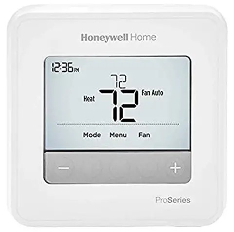
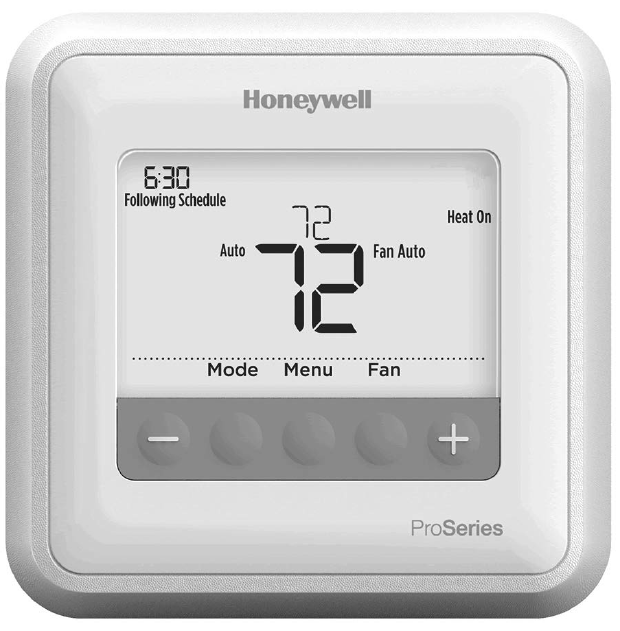
The Honeywell TH4110U2005 is a T4 Pro programmable thermostat designed for conventional heating and cooling systems and compatible heat pump applications. This user guide also covers the TH4210U2002 model.

Model: TH4110U2005
Series: Honeywell T4 Pro
Document: User Guide
Document Number: 33-00188EFS
Format: PDF
Language: English, French, Spanish

The guide explains how to use the thermostat’s buttons and display, change temperature settings, select Heat or Cool, adjust the fan, and program a heating and cooling schedule. It also covers temporary temperature changes, Hold settings, and basic thermostat operation.

Check the model number on your thermostat before using this guide. The TH4110U2005 is the 1 Heat / 1 Cool version, while the related TH4210U2002 supports different system configurations.

Honeywell Home TH6220WF2006 T6 Pro Smart Installation Manual

Professional installation guide for the Honeywell Home T6 Pro Smart Programmable Thermostat, model TH6220WF2006. This manual also covers the TH6320WF2003 model.

Brand: Honeywell Home
Series: T6 Pro Smart
Models: TH6220WF2006, TH6320WF2003
Document: Professional Install Manual
Document Number: 33-00392EFS-03
Format: PDF
Language: English, French, Spanish

The guide covers the UWP mounting system, optional decorative cover plate, thermostat wiring, terminal connections, and installer setup. It also includes wiring diagrams and instructions for configuring the thermostat with compatible heating and cooling equipment.

Before installation, check system compatibility. This thermostat requires 24 VAC power with a C wire and is not designed for 120–240V electric baseboard heating or millivolt systems. Installation and wiring should follow the manufacturer’s instructions.

Honeywell T4 Pro Programmable Thermostat Installation Manual

Honeywell T4 Pro Programmable Thermostat Installation Manual

Installation instructions for the Honeywell T4 Pro Programmable Thermostat, covering models TH4110U2005 and TH4210U2002.

Models: TH4110U2005, TH4210U2002
Document: Installation Instructions
Document Number: 33-00187EFS
Format: PDF
Pages: 36
Language: English, French, Spanish

This manual covers the T4 Pro thermostat installation, including the UWP mounting system, optional cover plate, terminal wiring, wiring diagrams, and installer setup. It also includes instructions for mounting the thermostat and checking the installation.

Check your thermostat model before using this document. The TH4110U2005 and TH4210U2002 have different heating and cooling system capabilities. Follow the wiring diagram that matches your equipment.

Honeywell Home T9 WiFi Smart Thermostat Installation Guide

Honeywell Home T9 WiFi Smart Thermostat Installation Guide

This walkthrough follows the official Honeywell Home T9 Wi-Fi Smart Thermostat Installation Guide (model RCHT9510WFW2001W, document 33-00421EF), the install-and-start half of the T9 paperwork: what is in the box, the compatibility and electrical check, removing the old unit, mounting and wiring the base, restoring power, joining Wi-Fi and pairing the wireless room sensors, then a short troubleshooting list and the warranty. Two things decide the install: whether you have a C-Wire, and how you pair the room sensors. The steps below track the guide’s own order, and the PDF is linked here. Turn off power at the breaker before you touch any wire.

Download the T9 Wi-Fi Thermostat Installation Guide (PDF)

Table of Contents

Before You Start: Compatibility, Cautions and Tools

The guide’s compatibility section is specific. The T9 works with most heating, cooling and heat pump systems on 24V, and it will not work with:

  • Electric baseboard heat (120–240V line voltage).
  • Millivolt systems, such as gas-fire heaters that run without a transformer.
  • Systems that need wired S terminals for indoor or outdoor sensors; it uses its own wireless room sensors instead.

It also needs an Android or iOS phone or tablet to set up the app, and the electrical rating is 24V at 60Hz, 0.2A.

The guide then lays out cautions and kit. Disconnect power before installing, since this is electrical work; compressor protection is bypassed during the test step, so do not cycle the compressor quickly; and if the old thermostat contains mercury in a sealed tube, recycle it through your local waste authority rather than binning it. At end of life, the thermostat itself is electronic waste. In the box are the T9, a UWP wall plate, screws and anchors, the wireless room sensor and the printed guide. Tools: a Phillips and a small flat-head screwdriver, needle-nose pliers, a wire stripper, a pencil, a drill with a 7/32-inch bit, a level and a flashlight. You also need your home Wi-Fi password, and the C-Wire Adapter if you go that route.

The C-Wire, and the Adapter When You Don’t Have One

A C-Wire (common wire) is required for the T9, because Wi-Fi thermostats draw constant 24 VAC power. The guide says plainly that if there is no C-Wire at the wall, an included C-Wire Adapter can be installed in its place (Step 10). One note the guide repeats: there is no universal wire color for the C, so identify wires by the terminal letter on your old thermostat, not by color.

To see whether you already have a spare for the C terminal, the guide has you check the wires coming from the wall against the terminals in use; a labeled-but-unconnected wire is the usual candidate for C, and the adapter is the fallback when there is none.

Installing the T9: Remove, Mount and Wire

First take the old unit out (Step 2 onward):

  1. Turn off power at the breaker box or the switch that controls the heating and cooling equipment. The guide warns that the thermostat’s own on/off switch does not cut power to the equipment.
  2. Confirm the system is off by changing the temperature on the old thermostat and checking that nothing starts.
  3. Take the old thermostat off its wall plate, leaving the wires in place, and photograph the wiring from several angles; you will reference this image later.
  4. Remove any jumpers (small staples or short wires linking two terminals). Do not reuse them; the T9 does not need jumpers, so keep them with the old wall plate.
  5. Label each wire with the supplied stickers by its terminal letter. Do not label the jumpers.

Then mount and connect. Level the new wall plate over the wire hole, mark and drill (7/32-inch), tap in the anchors and fasten the plate. Connect each labeled wire to the terminal that carries the same letter, and fit the C wire (or the adapter) on the C terminal. For a heat pump, verify there is not a wire on the W terminal of the wall plate, because cooling runs from a call for heat on that configuration. After the wires are in, snap the thermostat body onto the plate and restore power at the breaker.

Wi-Fi, the App and Room Sensors

Once powered, the T9 walks you through joining your home Wi-Fi network and finishing setup in the Honeywell Home app; that needs your Wi-Fi password. The T9’s signature feature is room prioritization: you add the included wireless room sensors, and rooms where motion is detected feed an averaged temperature for the house, while rooms with no detected activity are left out. To pair a sensor, press and hold its Connect button for 15 seconds until the LED turns amber, then on the thermostat go to Menu and Devices and Sensors and follow the on-screen prompts to add it.

Troubleshooting

These are the guide’s own troubleshooting items (p.16), listed by symptom; the advice column is what the guide says to try.

Problem What the guide says to do
Display is blank Check and reset the circuit breaker; make sure the heating/cooling power switch is on; make sure the furnace door is closed securely; make sure the C wire is connected.
Heating or cooling does not respond Go to Menu > System Mode and set Heat (with the target above the indoor temperature) or Cool (below it), then Done. Check the breaker, the power switch and the furnace door, and wait about 5 minutes for the system to respond.
Temperature setting will not change Bring the target inside the allowed ranges: Heat 40°F to 90°F (4.5°C to 32.0°C); Cool 50°F to 99°F (10.0°C to 37.0°C).
Aux heat runs while cooling For a heat pump, verify there is no wire attached to the W terminal of the wall plate; on this wiring, cooling runs from a call for heat.
A room sensor will not connect Press and hold the sensor’s Connect button for 15 seconds until the LED turns amber, then on the thermostat open Menu and Devices and Sensors and follow the on-screen steps to add it.

Specifications and Warranty

  • Model: RCHT9510WFW2001W (Honeywell Home T9 Wi-Fi).
  • Electrical: 24V at 60Hz, 0.2A; a C-Wire or the supplied C-Wire Adapter is required.
  • Systems: most heating, cooling and heat pump systems; not 120–240V electric baseboard and not millivolt.
  • Sensors: uses wireless room sensors, not wired S terminals.
  • Setpoint range: Heat 40°F to 90°F; Cool 50°F to 99°F.
  • Compressor protection: about a 5-minute wait after a change (bypassed only during the install test).
  • Warranty: a two-year limited warranty; Resideo Customer Care at 1-800-633-3991, with setup help at honeywellhome.com/support.

FAQ

Can I install the T9 without a C-Wire?

You can, using the included C-Wire Adapter. It needs 24V common power for Wi-Fi, and the guide’s Step 10 covers fitting the adapter when no C-Wire runs to the wall.

Will the T9 work on electric baseboard or a millivolt fireplace?

No. The guide lists 120–240V electric baseboard and millivolt systems as not compatible, and warns against line-voltage wiring (thick black wires with wire nuts).

Why does the guide say not to reuse jumpers?

The T9 does not need the old jumpers, so the guide has you leave them with the old wall plate and label only the real wires.

How do the wireless room sensors set the temperature?

Rooms where the sensors detect motion contribute to an averaged reading, and rooms with no detected activity do not, so the thermostat follows the rooms you use.

How long is the warranty?

The guide states a two-year limited warranty from the date of first purchase, excluding the battery, handled through Resideo Customer Care at 1-800-633-3991.

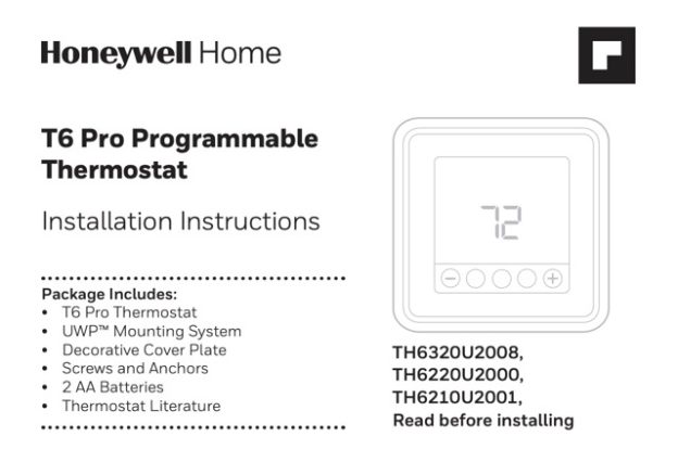
Honeywell T6 Pro Programmable Thermostat Installation Manual

Honeywell T6 Pro Programmable Thermostat Installation Manual

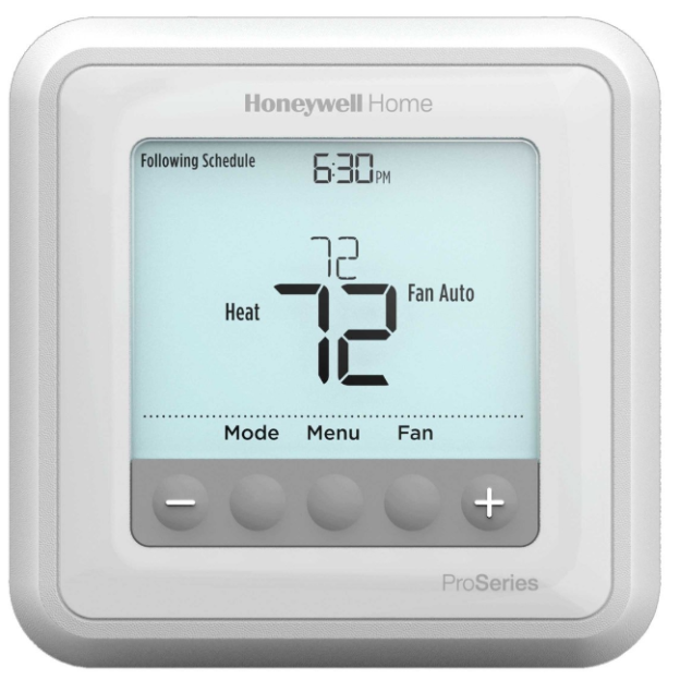
The Honeywell T6 Pro Programmable Thermostat Installation Manual is Honeywell Home’s technician-facing booklet for the T6 Pro touchscreen programmable thermostat. The current printing carries document number 33-00181EFS (revision 33-00181EFS-19, M.S. Rev. 05-22, © 2022 Resideo Technologies, Inc.). The English section runs pages 1 to 14, with French following and Spanish at the back, and the three model numbers it covers are TH6320U2008, TH6220U2000, and TH6210U2001.

Where the guide says “shaded areas apply only to TH6320U / TH6220U” or “(TH6320U only),” read that as a real limit: the smaller TH6210U is a single-compressor model and does not carry the second-stage, sensor, and dual-fuel options. The installer-setup table below shows which functions are gated to a specific model so you do not chase an option that does not exist on the unit in front of you.

Download Honeywell T6 Pro Installation Instructions Manual (PDF)

Contents

Before You Start: Box, Tools, and Power

Page 1 lists what is in the box: the T6 Pro thermostat, the UWP™ Mounting System, a decorative cover plate, screws and anchors, two AA batteries, and the thermostat literature. The cover plate comes in two physical shapes and the guide walks each one:

  • Square cover plate. Separate the cover plate from its mounting plate, fix the mounting plate to the wall using any of its eight screw holes, hang the UWP on the top hook, snap the bottom of the UWP in, then snap the cover plate onto the mounting plate.
  • Rectangular cover plate. Mount the cover plate directly to the wall with any of its six screw holes, hang the UWP on its top hook, and snap the UWP bottom into place.

Drill sizes are fixed by anchor color: 7/32 in (5.6 mm) for the red anchors and 3/16 in (4.8 mm) for the yellow anchors, with #8 1-1/2 in (38 mm) screws for red and #6 1-1/2 in (38 mm) for yellow. Page 2 opens every mounting path with the same rule: turn the power off at the breaker box or the system switch before you do anything else.

Terminals, Power Options, and the Slider Tabs

The UWP carries a wide set of terminals, but not all of them are live on the T6 Pro. The guide is explicit about which are used and which are “Not used for T3 thermostat” on the smaller variants. This is the reference table:

Terminal Function
R 24 VAC power from the heating transformer (jumpable via R slider tab)
Rc 24 VAC power from the cooling transformer (jumpable via R slider tab)
C 24 VAC common; on two-transformer systems, from the cooling transformer
W Heat stage 1. Do not use this terminal for heat pump applications
W2 / AUX Auxiliary heat, or Heat stage 2 on conventional multistage systems
Y Compressor contactor, stage 1
Y2 Compressor contactor, stage 2
G Fan
O/B Heat pump changeover valve
E Emergency heat (TH6320U)
L/A Heat pump fault input; the common (C) wire is required when L/A is used
S Wired indoor or outdoor sensor input (TH6320U / TH6220U only)
K, U Unused

The R/Rc slider tab is the built-in jumper on the UWP. If you have only one R wire, no matter whether it landed on R, Rc, or Rh on the old base, leave the slider in the up (one-wire) position. If you have separate wires on R and Rc, move the slider to the down (two-wire) position. The guide adds one T6 Pro specific instruction: the U-terminal slider tabs should be left in place.

Power options. The R and C terminals are the primary 24 VAC supply; the C terminal is optional only because the two AA batteries can carry the thermostat on their own, and the guide still recommends wiring C. Insert the two AA cells for primary power on battery-only installs, or as backup power alongside 24 VAC.

Wiring Diagrams by System Type

Pages 4 and 5 print the wiring diagrams the installer matches to the equipment. The conventional set on page 4 covers 1H/1C with one or two transformers, heat-only, heat-only with fan, heat-only Series 20 (radiant zone valve wiring), heat-only power-open zone valve, cool-only, and 2H/2C with one transformer. The heat pump set on page 5 covers 1H/1C, 2H/1C with auxiliary and emergency heat, 2H/2C, 3H/2C, and Dual Fuel. Model limits the guide prints:

  • The second compressor stage (Y2) and the auxiliary/emergency heat pair (AUX and E) apply on the larger heat-pump models. The 3H/2C and the Y2-equipped Dual Fuel arrangements are called out as TH6320U only.
  • Where the old base has separate wires on AUX and E, both go into the combined E/AUX terminal; a wire that ran to AUX with a jumper over to E is handled the same way and needs no jumper on the T6 Pro.
  • Wire specification printed on both pages is 18- to 22-gauge thermostat wire; shielded cable is not required.

The Series 20 and power-open-zone-valve arrangements come with an ISU pairing: in the Installer Setup, set Heat system type to Radiant Heat and Cool stages to 0 (notes [5]). The 2H/2C conventional system uses note [6]: in Installer Setup, set system type to 2 Heat / 2 Cool Conventional. Reversing valve polarity is note [7]: set the changeover valve in Installer Setup to O (cool changeover) or B (heat changeover). The heat-pump stage counts are notes [8], [9], and [10]; they pick which compressor and backup-heat combination ISU 200, 220, 221, and 255 have to match.

Mounting the UWP and the Thermostat

Pages 2 and 6 combine into a short physical sequence. Turn off the breaker or system switch. Position the UWP, level it, mark the holes, drill to the anchor color, and tap the anchors flush. Pull open the UWP door, feed the wires through the wiring hole, place the UWP on the anchors, tighten the mounting screws with the correct screw size for the anchor color until the plate no longer moves, and close the door. On page 6 the guide tells you to push any excess wire back into the wall opening, close the door so it does not bulge, align and snap the thermostat onto the UWP, and only then restore power at the breaker or switch.

With power back on, page 6 covers the first-time set of clock and date. Press Menu, arrow to TIME (12 or 24 hour format, hour, minutes), then DATE (year, month, day). Pressing Select at each step saves and advances.

Installer Setup (ISU) Reference

Page 8 opens the ISU section with the entry key: press and hold CENTER together with the second button shown on page 8 for about three seconds to enter the advanced menu, then Select to enter ISU. Cycle options with Select, change values with the up/down arrows, and press Home when you are done to save and return to the Home screen. The guide’s full list runs pages 8 to 10; defaults shown in bold are the ones the manual marks as the shipped values. Model-gated rows are called out. The functions installers change most:

ISU Name Options and model notes
120 Scheduling options 0 non-programmable, 2 = 5-2, 3 = 5-1-1, 4 = 7-day
125 Temperature indication scale 0 = Fahrenheit, 1 = Celsius
130 Outdoor sensor 0 none, 1 wired (TH6320U / TH6220U only)
200 Heating system type 1 conventional forced air, 2 heat pump, 3 radiant, 5 none (cool only)
205 Heating equipment type Forced air 1-5 (standard gas, high-efficiency gas, oil, electric, hot-water fan coil); heat pump 7 air-to-air or 8 geothermal; radiant 9 hot water or 12 steam
218 Reversing valve O/B 0 = O (energized in Cool), 1 = B (energized in Heat)
220 Cool / compressor stages 0, 1, or 2 (TH6210U is single-compressor only; TH6220U on a heat pump is also limited to one)
221 Heat / backup heat stages Heat 1 or 2; backup 0 or 1
230 Fan control in Heat 1 equipment controls fan, 2 thermostat controls fan (shown when ISU 205 is electric forced air or fan coil)
253 Aux/E terminal control 0 drive both together, 1 independent; fixed at 0 on every model except TH6320U
255 Backup heat source (heat pump) 1 electric forced air, 2 gas/oil (fossil) forced air (TH6320U / TH6220U only)
256 Emergency heat source 1 electric forced air, 2 gas/oil (fossil) forced air (TH6320U only)
260 External fossil fuel kit 0 thermostat controls backup heat, 1 external kit controls it (TH6320U / TH6220U only)
300 System changeover 0 manual, 1 automatic (turns on the Auto system mode on the Home screen)
303 Auto changeover differential 0 to 5 °F (0 to 2.5 °C); the guide notes this is not deadband, whose value is fixed at 0 °F by firmware
340 Backup heat droop 0 comfort or 2 to 15 °F; the comfort setting is available only when ISU 255 backup heat is electric
350 Upstage timer to backup heat Off, 30 min up to 16 hours
355, 356 Compressor lockout / balance point and outdoor lockout backup heat Off or 5-60 °F / 5-65 °F in 5 °F steps; use a wired outdoor sensor to configure (TH6320U / TH6220U)
365, 366 Compressor cycle rate, stages 1 and 2 1 to 6 cycles per hour
370, 371 Heating cycle rate, stages 1 and 2 1 to 12 CPH
375 Heating cycle rate auxiliary 1 to 12 CPH
378 Heating cycle rate emergency 1 to 12 CPH (TH6320U only)
387 Compressor protection Off, or 1 to 5 minutes of minimum off time
425 Adaptive Intelligent Recovery 0 no, 1 yes; runs equipment early so the room hits the setpoint on schedule
430, 431 Minimum cool setpoint, maximum heat setpoint Cool 50 to 99 °F (default 50 °F), Heat 40 to 90 °F (default 90 °F)
435 Keypad lockout Series 0-6 (older T6): 0 none, 1 partial, 2 full. Series 7 (current): 0 disabled, 1 enabled; when disabled the menu lockout option disappears entirely
500, 515, 520 Indoor sensor wiring, type, and control source TH6320U / TH6220U only: 500 no/yes wired; 515 10k or 20k; 520 1 thermostat only, 2 wired only, or 3 average
702, 711, 712 Air filter count and each filter’s replacement reminder 0 to 2 filters; interval per filter from 0 (off) through run-time days (10 to 150) and calendar days/months (30 days up to 15 months)
1400, 1401 Backlighting and its brightness 0 on demand, 1 continuous (needs a C wire); brightness 1 to 5 shown only when continuous is selected
1410, 1415 Clock format and daylight saving time 12 or 24 hour; DST 0 off, 1 on
1420 Temperature display offset -3 to +3 °F or -1.5 to +1.5 °C (0 means the display is unaltered)

Installer System Test

Page 11 walks the same entry path as ISU, then arrow to TEST and press Select. Inside the test, arrow to switch between Heat, Cool, Fan, Em Heat, and Ver (the firmware version screen). Press Select and use the arrows to bring each stage on and off one at a time, and press Home to exit. The status codes the guide prints: Heat 0 all off, 1 stage 1 on, 2 stage 2 on, 3 stage 3 on; Cool 0 all off, 1 stage 1 on, 2 stage 2 on; Em Heat 0 off, 1 on; Fan 0 off, 1 on. The stage 2, stage 3, and the Em Heat rows apply to the larger heat-pump models; on the TH6210U and other single-stage conventional setups those steps do not appear.

Specifications and Electrical Ratings

Page 12 is the specification block:

Item Value from the manual
Heat setpoint range 40 to 90 °F (4.5 to 32.0 °C)
Cool setpoint range 50 to 99 °F (10.0 to 37.0 °C)
Working ambient 32 to 120 °F (0 to 48.9 °C)
Operating ambient 37 to 102 °F (2.8 to 38.9 °C)
Shipping temperature -20 to 120 °F (-28.9 to 48.9 °C)
Operating relative humidity 5% to 90% non-condensing
Physical size (H × W × D) 4-1/16 in × 4-1/16 in × 1-5/32 in (103.5 × 103.5 × 29 mm)
Terminal voltage, all outputs 20 to 30 VAC, 50/60 Hz
Running current, W / W2 (Aux) / Y / Y2 0.02 to 1.0 A
Running current, E / G / O/B / L/A 0.02 to 0.5 A
Wire gauge, unshielded 18 to 22

Safety and Disposal Notices

Page 14 prints four cautions that belong in any installer handoff. They are quoted here exactly:

CAUTION: ELECTRICAL HAZARD. Can cause electrical shock or equipment damage. Disconnect power before beginning installation.

CAUTION: EQUIPMENT DAMAGE HAZARD. Compressor protection is bypassed during testing. To prevent equipment damage, avoid cycling the compressor quickly.

CAUTION: MERCURY NOTICE. If this product is replacing a control that contains mercury in a sealed tube, do not place the old control in the trash. Contact your local waste management authority for instructions regarding recycling and proper disposal.

CAUTION: ELECTRONIC WASTE NOTICE. The product and batteries should not be disposed of with other household waste. Check for the nearest authorized collection centers or authorized recyclers. The correct disposal of end-of-life equipment will help prevent negative consequences for the environment and human health.

Troubleshooting

Page 13 is the guide’s own troubleshooting table. It is reproduced below with only what the manual states.

Problem What the manual advises
Display is blank Check the circuit breaker and reset if necessary. Confirm the power switch for the heating and cooling system is on. Confirm the furnace door is closed securely. Confirm two fresh AA alkaline batteries are correctly installed (see page 3).
Heating or cooling system does not respond Press Mode to set System to Heat (page 7) and confirm the desired temperature is above the indoor temperature. To test cooling, press Mode to set System to Cool and confirm the desired temperature is below the indoor temperature. Check the circuit breaker and reset if necessary. Confirm the heating and cooling power switch is on. Confirm the furnace door is closed securely. Wait five minutes for the system to respond.
Temperature settings do not change Confirm the setpoints are inside the ranges the guide lists: heat 40 to 90 °F (4.5 to 32.0 °C), cool 50 to 99 °F (10.0 to 37.0 °C).
“Cool On” or “Heat On” is flashing Compressor protection is engaged. Wait five minutes for a safe restart without damaging the compressor.
Auxiliary heat runs during cooling For heat pump systems, verify there is no wire attached to W on the UWP. See “Wiring heat pump systems” on page 5.
Cool runs on a call for heat For heat pump systems, verify there is no wire attached to W on the UWP. See “Wiring heat pump systems” on page 5.

Getting Help

The back-page customer assistance block on page 14 points installers to customer.resideo.com and to Resideo Customer Care at 1-800-468-1502, and the FCC statement is available at the same Resideo support path. The mailing address printed in the same footer is Resideo Technologies Inc., 1985 Douglas Drive North, Golden Valley, MN 55422. The identifier to quote when you call is the document marking on the booklet cover, 33-00181EFS-19, plus the model number on the back of the thermostat (TH6320U2008, TH6220U2000, or TH6210U2001).

Because this booklet is the installation guide, homeowner-side operation (schedules, overrides, alerts, and cleaning) is documented in the matching T6 Pro user guide, not here. If your question is about how the thermostat behaves day to day, ask the installer for that guide or download it separately.
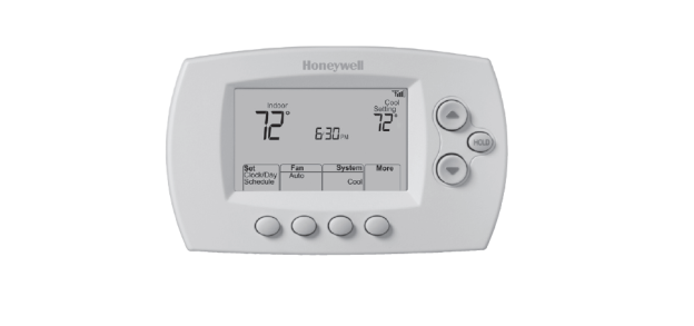
Honeywell RTH6500WF Wi-Fi Programmable Thermostat User Guide

Honeywell RTH6500WF Wi-Fi Programmable Thermostat User Guide

The Honeywell RTH6500WF Wi-Fi Programmable Thermostat User Guide is Honeywell Home’s owner manual for the RTH6500WF Smart Series 7-day programmable thermostat. The document number printed in the guide is 69-2715EF-07 (© 2018 Resideo Technologies, Inc.). It covers the touchscreen-style model with Wi-Fi and Total Connect Comfort, and it is the same guide used for the closely related RTH6580WF model. This page walks through what that guide contains and the facts most owners and installers look up.

Download rth6580wf1001-u-wi-fi-7-day-programmable-thermostat.pdf

Contents

Before You Start: Box, Power, and Compatibility

The first page of the guide lists what comes in the box: the thermostat with the wallplate attached, screws and anchors, a Quick Start Guide, the Thermostat ID Card, wire labels, the User Guide, and a Quick Reference Card. The ID Card matters later: it carries the MAC ID and MAC CRC you need to register online.

Two compatibility rules decide whether this thermostat fits your system at all:

  • It works with common 24-volt systems, including forced air, hydronic, heat pump, oil, gas, and electric.
  • It does not work with millivolt systems (such as a gas fireplace) or with 120/240-volt systems (such as baseboard electric heat).

A C (common) wire is required. The guide states plainly that the C wire is the primary power source and that without it the thermostat will not power up; if you have no C wire, it points you to its alternate-wiring videos rather than improvising. Two safety notes are printed on the inside cover and should be read before mounting:

MERCURY NOTICE: Do not place your old thermostat in the trash if it contains mercury in a sealed tube. Contact the Thermostat Recycling Corporation at www.thermostat-recycle.org or 1-800-238-8192 for information on how and where to properly and safely dispose of your old thermostat.

NOTICE: To avoid possible compressor damage, do not run air conditioner if the outside temperature drops below 50°F (10°C).

Installing and Wiring the RTH6500WF

Installation runs step 1 through step 13 across pages 3 to 9. The guide’s own sequence:

  1. Switch the power off to the heating/cooling system at the breaker box or the system switch.
  2. Remove the old faceplate leaving wires connected, and photograph the connections before disconnecting anything.
  3. Label each wire with the supplied tags by its old terminal designation, never by wire color.
  4. Remove the old wallplate, then separate the new thermostat from its wallplate using the finger holds.
  5. Mount the new wallplate (drill 3/16-inch holes for drywall or 7/32-inch for plaster if new anchors are needed).
  6. Wire the thermostat, starting with the C wire, then attach the body, insert the quick-reference card, and restore power.
  7. Set the clock to the current day and time, and set the system type before testing.

Two wiring details are easy to miss and the guide calls them out. On heat pump systems, if the old thermostat had separate wires on AUX and E, both go into the single E/AUX terminal with no jumper. The K terminal is marked for future use, so leave it empty. For most conventional installs, keep the metal jumper between R and RC in place and remove it only if you must connect both R and RC wires.

The guide also warns that the heating/cooling system type must be set correctly or the thermostat can run the equipment wrongly. A conventional single-stage system can proceed straight to Wi-Fi setup; a multistage system, any heat pump, or a hydronic system requires you to set system function 1 first.

Connecting to Wi-Fi and Registering Online

Wi-Fi setup (pages 10 to 11) happens from the thermostat itself, which broadcasts a network named NewThermostat followed by numbers. You join that network from a tablet, laptop, or phone, then open a browser to reach the setup page (the guide’s address is http://192.168.1.1), pick your home network from the list, and enter its password. While joining, the screen flashes Wait for up to three minutes, then shows Wi-Fi Setup Connection Success and displays signal strength in the top-right corner.

Registration is separate from connecting (pages 12 to 13). To use remote access you create a Total Connect Comfort account at mytotalconnectcomfort.com, confirm the activation email, then add the thermostat using its unique MAC ID and MAC CRC. The guide notes these identifiers are on the Thermostat ID Card or on the back of the unit, and that they are not case sensitive. When registration succeeds, the site shows SUCCESS and the thermostat shows Setup Complete for about 90 seconds.

Software updates arrive on their own over Wi-Fi; during an update the screen shows Updating with a percentage, and your settings are kept.

Daily Operation and Scheduling

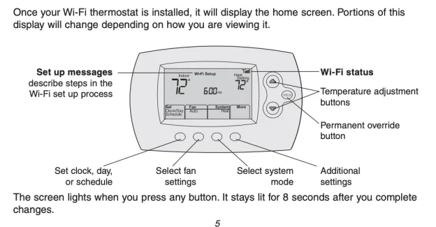
The home screen backlights for 8 seconds after any button. The buttons are the temperature up/down arrows, HOLD, and the Set Clock/Day/Schedule, Fan, and System soft-keys. The guide ships with four preset energy-saving periods:

Period Time Default heat Default cool
Wake 6:00 am 70° 78°
Leave 8:00 am 62° 85°
Return 6:00 pm 70° 78°
Sleep 10:00 pm 62° 82°

Fan mode toggles between Auto (runs only during heating or cooling) and On (continuous). System mode cycles through Heat, Cool, Off, Auto, and, on heat pumps with auxiliary heat, Em Heat; the guide notes not every mode appears on every installation. To edit a schedule you press Set Clock/Day/Schedule then Set Schedule, and step through each day and period with the arrows, pressing Next and Done; check that the thermostat is already in the mode (Heat or Cool) you intend to program. A single arrow press is a temporary override that lasts until the next period, and Cancel restores the schedule; HOLD is the permanent override that turns the schedule off until you cancel it.

Special Features

Page 17 describes three behaviors that owners ask about most:

  • Smart Response Technology learns how long the system takes to reach a setpoint and starts early so the room is comfortable at the scheduled time; the screen shows Recovery while it runs. Controlled by function 13.
  • Compressor protection forces the compressor to wait a few minutes before restarting; Cool On (or Heat On on a heat pump) flashes during that wait.
  • Auto changeover lets one Auto mode handle both heating and cooling, keeping the heat and cool setpoints at least 3 degrees apart. Controlled by function 12.

System Setup Functions

To enter system setup, press the Fan button and the up arrow together for about three seconds; the screen then shows a function number on the left and its option on the right, navigated with Next and adjusted with the arrows. The main functions listed on pages 18 to 19:

Function Purpose
1 System type (heat/cool, heat pump with or without backup, heat only, cool only, and the multistage combinations)
2 Heat pump changeover valve (O for cooling changeover, B for heating changeover)
3 Heating fan control (gas/oil versus electric)
5, 6 Heating cycle rate for stage 1 and stage 2 (matches equipment: steam/gravity, hot water or high-efficiency, standard gas/oil, electric)
12 Manual/auto changeover
13 Smart Response Technology on/off
14 Temperature format, Fahrenheit or Celsius
16 Schedule on/off (7-day programmable)
36 Device name for remote viewing
38 Wi-Fi on/off (turning it off removes the Wi-Fi Setup message)
39 Wi-Fi connection (set to 0 to disconnect the network)
42 Show or hide period and day on the home screen
85, 90 Restore the energy-saving schedule defaults; restore original settings (disconnects Wi-Fi and clears customizations)

Frequently Asked Questions

Page 20 answers these common ones:

  • Yes, the thermostat keeps running your heating and cooling with or without Wi-Fi; remote features are the only thing lost.
  • The MAC ID and MAC CRC are on the ID Card in the box or on the back of the thermostat, and each unit’s pair is unique.
  • If you cannot see the Wi-Fi Setup page, you are probably connected to the router and not the thermostat; reconnect to the thermostat.
  • Signal range can be extended with a Wi-Fi repeater or by configuring a standard router as a repeater.

Troubleshooting and Wi-Fi Error Codes

Pages 21 and 22 carry the guide’s own troubleshooting list. It is reproduced here with only what the manual states.

Problem What the manual advises
Display is blank Check and reset the circuit breaker; make sure the heating/cooling power switch is on; make sure the furnace door is closed securely; make sure the C wire is connected (page 6).
Cannot change system to Cool Check function 1 (System Type) so it matches your equipment.
Fan does not run when heat is called Check function 3 (Heating Fan Control) for the right gas/oil versus electric setting.
Cool On or Heat On is flashing Compressor protection is engaged; wait five minutes for a safe restart.
Heat pump blows cool in heat mode, or warm in cool mode Check function 2 (Heat Pump Changeover Valve) is set for your O or B valve.
Heating or cooling does not respond Set System to Heat and make sure the setpoint is above the indoor temperature (or Cool and below), then check the breaker, power switch, and furnace door, and wait five minutes.
Heating runs in cool mode, or heat and cool run together Check function 1; pull the thermostat off the wallplate and confirm bare wires are not touching; verify the wiring.

The Wi-Fi error codes on page 21 behave the same way: the manual’s code, meaning, and its stated action.

Code What the manual says to do
E01 Router lost power during Wi-Fi Setup; confirm the router is powered and working.
E02 Invalid Wi-Fi password (shows for 30 seconds, then returns to Wi-Fi Setup); re-enter the correct password.
E42 Router not issuing an IP address; wait up to 30 minutes, restart the thermostat off the wallplate for 10 seconds, and confirm the router assigns addresses.
E43 No internet connection; make sure the internet cable is plugged in and reboot the router.
E99 General error; take the thermostat off the wallplate for 10 seconds, then reattach.

If the no-Wi-Fi icon replaces the signal bars, the guide’s Lost Signal steps are to confirm Wi-Fi works on another device (and call your internet provider if not), move the router, and restart the thermostat by pulling it off the wallplate for 10 seconds before repeating the Wi-Fi setup.

Getting Help and Warranty

The guide directs owners to honeywellhome.com, and to call 1-855-733-5465 before returning the thermostat to the store. Additional FAQs live at honeywellhome.com/support. The document itself is 69-2715EF-07, and the limited warranty statement is on page 24 of the guide. For any service call, note the model number and the MAC ID/CRC, and, if a system-type problem is suspected, the current value of function 1, because those are the details the guide asks you to have ready.

Honeywell T6 Pro Programmable Thermostat User Manual

Honeywell T6 Pro Programmable Thermostat User Manual

The Honeywell T6 Pro Programmable Thermostat user guide is available as a PDF for models TH6320U2008, TH6220U2000, and TH6210U2001.

The guide explains how to operate the thermostat, change temperature settings, program a schedule, and use temporary or permanent Hold. It also covers the basic controls and system settings needed for everyday use.

Package Includes:

• T6 Pro Thermostat
• UWP Mounting System
• Honeywell Standard Installation Adapter (J-box adapter)
• Honeywell Decorative Cover Plate – Small; size 4-49/64 in x 4-49/64 in x 11/32 in (121 mm x 121 mm x 9 mm)
• Screws and anchors
• 2 AA Batteries
• Installation Instructions and User Guide

Models covered: TH6320U2008, TH6220U2000, TH6210U2001
File format: PDF
Language: English

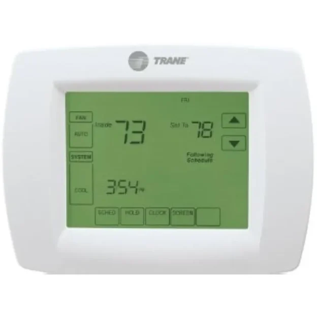
Trane TCONT802AS32DA

Trane TCONT802AS32DA Installation Instructions Manual

Download the installation instructions for the Trane TCONT802AS32DA touchscreen comfort control. The document also covers the related TCONT803AS32DA model.

Document number: 18-HD25D19-3
Format: PDF
Language: English

About This Manual

This installation manual is intended for technicians installing or replacing a compatible Trane comfort control. It covers thermostat placement, wiring, equipment setup, and installation checks. The exact configuration depends on the heating and cooling system connected to the control.

The instructions include guidance on thermostat location. For reliable temperature readings, placement should follow the manufacturer’s recommendations and avoid areas affected by drafts or unusual heat sources.

Online Reading & Download Installation Instructions

Skip to PDF content

Before beginning installation, confirm the model number and follow the complete instructions for the equipment being serviced. Thermostat wiring and system configuration should be handled by a qualified HVAC technician.

How to Use a Honeywell Thermostat

How to Use a Honeywell Thermostat: A Simple Guide

If you want to turn on the heat, adjust the air conditioning, or stop your thermostat from changing the temperature automatically, start with the controls on the front of the unit.

Honeywell thermostats come in several designs, from simple button-operated models to touchscreen and Wi-Fi thermostats. The controls may look different, but the basic settings are often similar.

1. How to Change the Temperature

Look at the display for the current room temperature and the temperature setting.

  • Press + or −, or use the up and down arrows to adjust the target temperature.
  • On a touchscreen model, tap the displayed temperature or use the on-screen controls.
  • Give your heating or cooling system time to respond after making a change.

The temperature you select is the target temperature, not necessarily the current room temperature.

2. Choose Heat, Cool, or Off

Find the System button or the system-mode menu. Depending on your model and HVAC setup, you may see these options:

  • Heat: Runs the heating system when needed.
  • Cool: Runs the air conditioning when needed.
  • Auto: Switches between heating and cooling automatically, if supported.
  • Off: Turns off normal heating and cooling operation.

For everyday use, choose Heat in cold weather or Cool when you need air conditioning. If your thermostat offers additional modes, check the model’s manual before using them.

3. What Do Fan Auto and On Mean?

The fan setting controls how the system’s blower operates.

  • Auto: The fan generally runs when heating or cooling is active.
  • On: The fan runs continuously, even when the system is not actively heating or cooling.

If you want the fan to run only when needed, Auto is usually the practical choice. Available settings vary by thermostat and HVAC system.

4. How to Stop the Thermostat from Changing Temperature

If the temperature keeps changing by itself, your thermostat may be following a programmed schedule.

Look for Hold, Permanent Hold, or a similar option to maintain your chosen temperature instead of following the normal schedule. On some models, changing the temperature creates only a temporary hold; other models use different controls.

To return to scheduled operation, look for Run, Resume Schedule, or the equivalent option on your thermostat.

5. Do You Need to Set a Schedule?

A programmable thermostat can use different target temperatures at different times of the day. For example, you might prefer a different setting while sleeping or when nobody is home.

To change the schedule, look for Schedule, Program, or Menu. The exact steps depend on the model.

If you prefer to adjust the temperature manually, check whether your thermostat offers a non-programmed mode or lets you override the schedule.

Quick Troubleshooting

The thermostat does not seem to respond. Check the selected system mode and temperature setting. If the display is blank, consult your model’s manual for power or battery checks.

The temperature keeps returning to an earlier setting. Check whether a schedule is active and whether the thermostat is using a temporary hold.

The heating or cooling does not start immediately. Some systems have a built-in delay. If the system still does not respond, consult the thermostat manual and your HVAC system’s instructions.

Find the Manual for Your Honeywell Thermostat

Need help with a specific Honeywell thermostat? Start by checking the model number on the device or its documentation. The exact controls and menu options can vary between models.

If you own the Honeywell RTH6580WF Wi-Fi thermostat, refer to the Honeywell RTH6580WF User’s Manual for model-specific instructions.

For other thermostats, search by the full model number to find the matching user manual. This is especially helpful when you need instructions for programming a schedule, adjusting settings, or using Wi-Fi features.

Frequently Asked Questions

How do I use a Honeywell thermostat for the first time?

Select the appropriate system mode, set your preferred temperature, and check the fan setting. If the thermostat follows a schedule, review it to make sure it matches your routine.

Why does my Honeywell thermostat keep changing the temperature?

A programmed schedule or temporary hold may be responsible. Check the schedule and hold settings for your specific model.

Where can I find instructions for my thermostat?

Find the model number on the device or its paperwork, then search for the matching user manual.