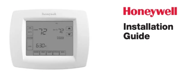
Search for the Honeywell Thermostat TH8320U1008 Install Manual and you will most often reach Honeywell’s official VisionPRO TH8000 Series Installation Guide (document number 69-2693). That single manual covers the touch-screen programmable models TH8110U, TH8320U, and TH8321U, so the wiring, installer setup, and safety guidance you need for the TH8320U are all inside it. The TH8320U is rated in the guide “for up to 3 Heat / 2 Cool systems” and can be configured for either multi-stage conventional or heat pump systems.
Here is what that manual covers, how it is organized, the safety notices to read before you start, and where to turn for help. It is written for homeowners, DIY installers, and HVAC technicians. One boundary worth stating early: Honeywell’s 69-2693 document is an installation and setup manual. Everyday front-panel operation, such as setting the schedule from the touch screen or adjusting comfort setpoints, is closely related but often published as a separate homeowner guide, so if you only need day-to-day operating steps, download both documents from the official support site.
The model number is not printed on the front. As the manual instructs, pull the thermostat from the wallplate and turn it over to find the model number. That confirms you have the correct TH8320U manual before you follow any wiring step.
Key Features
The TH8000 Series is a touch-screen, wall-mounted programmable thermostat built around staging control. The features below are drawn from the installation guide’s terminal tables, installer-setup function list, and “Special functions” page. Almost all of them live in the protected Installer Setup menu, which is separate from the homeowner screens.
System and staging capability
- Up to 3 heat / 2 cool stages. Installer options cover multistage conventional and heat pump configurations (setup function 0170 offers system types such as 2 heat/2 cool multistage conventional and 3 heat/2 cool heat pump with auxiliary heat).
- Conventional and heat pump systems. The wiring section provides two distinct terminal maps: one for conventional systems (W, W2, Y, Y2) and one for heat pumps (Y, Y2, Aux/E, O/B, L).
- Wide system-type support. The guide lists gas/oil/electric heat with air conditioning, warm air, hot water and high-efficiency furnaces, heat pumps, steam, gravity, two-wire zone-valve systems (Series 20), cool only, and 750 mV heating systems.
Comfort and intelligence features
- Adaptive Intelligent Recovery™ (function 0530) lets the thermostat “learn” how long your furnace and air conditioner take to reach a programmed temperature, so the space arrives at setpoint at the scheduled time.
- Automatic or manual changeover (functions 0300 and 0310). In auto mode the thermostat picks heat or cooling based on indoor temperature; the guide notes heat and cool settings must be at least 2°F apart (at least 5°F if dehumidification is enabled).
- Programmable schedule. Setup function 0160 selects 7-day programming or non-programmable, and function 0540 chooses either 4 program periods (Wake, Leave, Return, Sleep) or 2 periods (Wake, Sleep).
- Maintenance reminders. Furnace filter (0500), humidifier pad (0510), and UV lamp (0520) change reminders with selectable run-time or calendar intervals.
- Optional sensors. Terminals S1/S2 support an optional outdoor or remote indoor temperature sensor (function 0340) for display-only or control use.
- Compressor protection. Function 0580 forces a short delay (factory default 5 minutes) before the compressor restarts; during this delay the guide says the message “Wait” flashes on the display.
- Keypad lock. Function 0670 lets you partially or fully lock the touch screen, which is handy for property managers and rentals.
Dehumidification control (function 0380) is present in this shared manual but is specified for the TH8321U model, which the guide describes as the version “with dehumidification.” If the guide shades or flags a feature as TH8321-specific, assume it does not apply to your TH8320U.
Installer Setup functions at a glance
The features above are configured through Installer Setup. Use this index to jump to the right function number:
| Feature | Installer Setup function |
|---|---|
| System type | 0170 |
| Schedule format / program periods | 0160 / 0540 |
| Adaptive Intelligent Recovery | 0530 |
| Manual / Auto changeover | 0300 / 0310 |
| Compressor protection (“Wait”) | 0580 |
| Maintenance reminders (filter / humidifier pad / UV lamp) | 0500 / 0510 / 0520 |
| Keypad lock | 0670 |
| Remote / outdoor sensor (terminals S1/S2) | 0340 |
| Factory reset | 0710 |
Document Structure
Homeowners, installers, and service technicians each go to a different part of the 69-2693 guide, so it helps to know the order things appear in. The guide is compact and mostly diagram-driven. Its sections run in this sequence (numbering follows the printed installation guide).
- Cover & model scope. Lists the models covered (TH8110U / TH8320U / TH8321U), supported system types, the lithium/perchlorate battery notice, and the “Need Help?” contact block.
- Wallplate installation. How to separate the wallplate from the thermostat and mount it, including drill sizes (3/16″ for drywall, 7/32″ for plaster), wire hole, mounting screws, and wall anchors.
- Power options. Explains connecting the 24 VAC transformer common to the “C” terminal and inserting the supplied batteries for primary or backup power.
- Wiring — terminal designations. Side-by-side Conventional and Heat Pump terminal definitions (R, Rc, C, W, W2, Y, Y2, G, L, Aux/E, O/B, S1, S2).
- Wiring guides by system. Diagrams for conventional systems (1H/1C one- and two-transformer, heat only, heat only with fan, Series 20 zone valve, cool only, 2H/2C) and heat pump systems (1H/1C, 2H/1C and 2H/2C, 3H/2C with auxiliary heat), each with numbered notes such as “remove jumper for 2-transformer systems.”
- Mount & set date/time. Removing the tab, snapping the thermostat onto the wallplate, and setting the real-time clock.
- Installer setup. How to enter the setup menu (press SYSTEM, then hold SYSTEM + HEAT until the display changes) and a function table (0120 through 0710) covering year/date, system type, fan control, changeover valve, cycle rates, backlight, deadband, temperature unit, daylight savings, lockouts, reminders, keypad lock, and reset.
- Installer system test. A “Test” mode that energizes cooling, fan, heating, and emergency-heat circuits so an installer can verify each output.
- Special functions. Plain-language notes on auto changeover, remote sensor, Adaptive Intelligent Recovery, compressor protection (“Wait”), dehumidification, and heat pump temperature lockouts.
- Accessories & replacement parts. Lists optional part numbers, including the outdoor temperature sensor (C7089U1006) and remote indoor sensor (C7189U1005).
- Specifications. Temperature ranges (heat 40–90°F, cool 50–99°F), operating and shipping temperatures, and electrical ratings per terminal (for example, W and Y rated 20–30 VAC).
A homeowner usually needs only section 6 (mounting and setting date/time); the daily schedule itself lives in Installer Setup (functions 0160 and 0540). An installer works from sections 3 through 5 (power, terminal designations, and the wiring guides) plus the setup table in section 7. For diagnosis, section 8 (installer system test) together with the terminal list in section 4 and the specs in section 11 answer most questions.
Important Safety Notices
The manual opens with several requirements that people tend to skim. The lines below are quoted from the installation guide; follow them rather than working from memory.
- Qualified installer required. The guide states the product “Must be installed by a trained, experienced technician,” and that “Failure to follow these instructions can damage the product or cause a hazardous condition.”
- Electrical hazard — disconnect power. “CAUTION: ELECTRICAL HAZARD. Can cause electrical shock or equipment damage. Disconnect power before beginning installation.” Treat the low-voltage circuit as live until you have confirmed power is off at the equipment.
- Mercury disposal. The manual’s Mercury Notice says that if you are replacing a control that contains mercury in a sealed tube, you must not put the old control in the trash; contact your local waste-management authority for recycling and disposal instructions.
- Lithium / perchlorate battery. The guide warns the thermostat “contains a Lithium battery which may contain Perchlorate material,” and that special handling may apply (it points to the California DTSC perchlorate page for guidance).
- Compressor test hazard. During system test the guide warns: “CAUTION: EQUIPMENT DAMAGE HAZARD. Compressor protection is bypassed during testing. To prevent equipment damage, avoid cycling the compressor quickly.”
- Wiring specifics that affect safety and equipment. The notes direct you to remove the factory jumper only for two-transformer systems, and warn that if the L terminal is used, the 24 VAC common (terminal C) must be connected. Following these prevents mis-staging and back-feed between transformers.
When to stop and call a professional: if you find damaged or unlabeled wires, no clean way to provide a proper common (C) connection, gas or oil equipment you are not licensed to service, or any sign of moisture at the wall opening. This article summarizes the official manual; when a step is unclear, refer to the original document or contact Honeywell/Resideo support rather than guessing.
Getting Help
The manual’s own “Need Help?” block gives the primary support path: for assistance with this product, Honeywell directs users to visit customer.honeywell.com or call Honeywell Customer Care toll-free at 1-800-468-1502. Because these Honeywell Home thermostats are now supported under the Resideo brand, official documentation and product support for the VisionPRO 8000 series can also be found by searching the Honeywell Thermostat TH8320U1008 Operating Manual page or the manufacturer’s support site for the model number.
Before you call, write down the model number (found inside the unit, as noted above), your system type (conventional or heat pump, and how many heat/cool stages), and the wiring you have. Take a photo of the wiring before anything is disconnected. If you are a homeowner who only needs operating help, ask specifically for the VisionPRO 8000 Homeowner/Owner’s Manual so you get the front-panel programming guide in addition to the installation guide.
Download PDF: Honeywell Thermostat TH8320U1008 Installation Manual.pdf