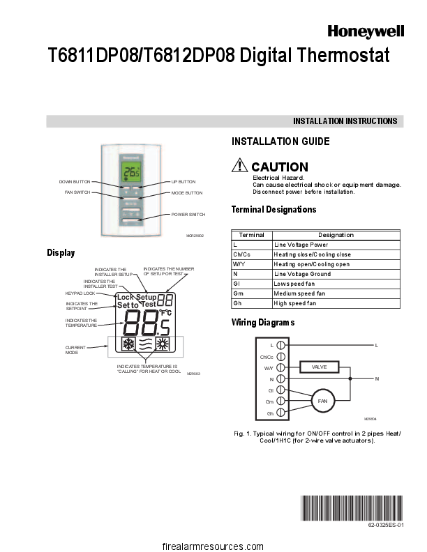
The Honeywell Digital Thermostat T6811DP08 User Manual helps technicians install, wire, configure and troubleshoot this non-programmable thermostat for two-pipe fan coil systems. This guide covers the installation document, terminal designations, operating controls, installer settings, test procedures and common faults. It also explains the electrical safety precautions required before working on this 110 VAC thermostat.
Quick Facts and Specifications
The T6811DP08 is a digital fan coil thermostat designed for manual heating and cooling selection, ventilation and three-speed fan control. It is relevant to building maintenance teams working with fan coil units in hotels, apartments, offices and similar facilities.
|
Specification |
T6811DP08 Details |
|---|---|
|
Model |
Honeywell T6811DP08 |
|
Supply voltage |
110 (+20%, −10%) VAC |
|
Supply frequency |
50/60 Hz |
|
System application |
Two-pipe fan coil |
|
Control modes |
Heat, Cool and Vent |
|
System selection |
Manual heating/cooling changeover |
|
Fan control |
Three speeds: Low, Medium and High |
|
Temperature setting range |
10–32°C |
|
Temperature control accuracy |
±1°C at 21°C |
|
Electrical load rating |
4(2) A |
|
Protection rating |
IP20 |
|
Operating temperature |
−18 to 49°C |
|
Installation |
Wall-mounted |
|
Mounting boxes |
86 × 86 mm or 2 × 4 inch junction box |
|
Programming |
Non-programmable; no seven-day schedule |
Important: The T6811DP08 is a line voltage thermostat, not a conventional 24 VAC low-voltage thermostat. Do not assume that wiring instructions for other Honeywell models apply to this unit.
Where to Download the Official Manual PDF
The principal installation document for this thermostat family is identified as 62-0325ES-01. It covers the T6811DP08 and T6812DP08 models.
Installation Instructions: 62-0325ES-01
This document is the primary reference for installation and servicing. It includes display indicators, terminal designations, wiring diagrams for two-wire and three-wire valve actuators, wall mounting, Installer Setup, Installer Test, normal operation and troubleshooting.
View the T6811DP08/T6812DP08 Installation Instructions PDF. This is an archived copy of a Honeywell-branded document, rather than a verified current manufacturer-hosted download.
Understanding the Display
|
Indicator |
Meaning |
|---|---|
|
Temperature |
Displays room temperature or the value selected by the display configuration. |
|
Setpoint |
Identifies the selected temperature setting. |
|
Current Mode |
Shows the active mode: Heat, Cool or Vent. |
|
Heating or Cooling Demand |
Indicates that the thermostat is calling for heating or cooling. |
|
Keypad Lock |
Indicates that keypad lockout is active. |
|
Setup |
Indicates Installer Setup mode. |
|
Test |
Indicates Installer Test mode. |
|
Setup/Test Number |
Identifies the configuration item or test function displayed. |
The display's appearance can vary according to the active mode and installer configuration.
Button and Switch Functions
- UP: In normal Heat or Cool operation, increases the selected temperature setpoint. It also changes values in Installer Setup and Installer Test modes.
- DOWN: Decreases the temperature setpoint or changes the value of the selected configuration item.
- MODE: Cycles through Heat, Cool and Vent.
- POWER switch: Turns the thermostat on or off.
- FAN switch: Selects Low, Medium or High fan speed.
In Vent mode, the fan operates without a heating or cooling demand from the thermostat. If a button appears unresponsive, check whether the thermostat is switched off, keypad lockout is active or Vent mode has been selected.
Terminal Designations and Wiring Diagram
Correct terminal identification is essential when installing or replacing a Honeywell T6811DP08.
|
Terminal |
Function |
Application |
|---|---|---|
|
L |
Line voltage power |
Incoming live supply |
|
Ch/Cc |
Heating close / Cooling close |
Valve actuator control |
|
W/Y |
Heating open / Cooling open |
Valve actuator control |
|
N |
Neutral supply connection |
Electrical supply common |
|
Gl |
Low-speed fan |
Fan motor low-speed input |
|
Gm |
Medium-speed fan |
Fan motor medium-speed input |
|
Gh |
High-speed fan |
Fan motor high-speed input |
Wiring terminology: The original document's extracted terminal table describes N as a line-voltage ground connection. Do not interpret this as permission to connect neutral and protective earth together. Confirm the actual supply and protective-earth requirements against applicable electrical regulations and verified manufacturer documentation before wiring.
Two-Wire Valve Actuator
The installation document includes a typical ON/OFF control arrangement for a two-pipe heating/cooling system with a two-wire valve actuator. The actuator wiring arrangement depends on its electrical design. Follow the manufacturer's diagram to identify the correct actuator connections and the terminals used for opening and closing. Do not infer a complete actuator circuit from terminal names alone.
Three-Wire Valve Actuator
The manual also illustrates a typical arrangement for a three-wire valve actuator. A three-wire actuator may use different connections for its control functions than a two-wire ON/OFF actuator. The exact connections depend on the actuator design and must match the wiring diagram supplied for that device.
Before connecting the valve, establish:
- Whether the actuator is designed for the available supply voltage.
- Which conductors provide the required control functions.
- Which thermostat terminals the verified diagram specifies.
- Whether the existing system is configured for heating or cooling.
Do not interchange two-wire and three-wire actuator wiring arrangements without confirming compatibility.
DANGER: 110 VAC LINE VOLTAGE — ELECTRIC SHOCK HAZARD
The T6811DP08 operates from a 110 VAC nominal supply. Contact with live conductors can cause serious injury or death.
- Disconnect the electrical supply before installation, wiring, inspection or maintenance.
- Verify that the circuit is de-energised using an appropriate test instrument.
- Do not treat this thermostat as a 24 VAC low-voltage device.
- Have installation and electrical troubleshooting performed by a qualified electrician or HVAC technician.
- Restore power only after all connections, covers and mounting screws have been checked.
Wiring Diagram Reference
Consult the wiring diagrams in document 62-0325ES-01 for the illustrated two-wire and three-wire actuator arrangements. Never use a generic fan coil wiring diagram as a substitute for the correct diagram for the installed valve, fan motor and supply arrangement.
Installation Steps
Step 1: Mount the Back Cover
Isolate the electrical supply. Pull the existing conductors through the wiring opening and position the back cover over the wall junction box. The thermostat is intended for installation on an 86 × 86 mm or 2 × 4 inch junction box, subject to confirmation of the actual mounting arrangement.
Step 2: Secure the Back Cover
Insert the mounting screws and tighten them securely. Check that the back cover sits correctly against the mounting surface without pinching or damaging conductors.
Step 3: Connect the Wires
Loosen the relevant screw terminals. Insert each conductor into its designated terminal and tighten the terminal screw. Verify every connection against the correct wiring diagram before proceeding.
Step 4: Fit the Thermostat Body
Align the top of the thermostat with the back cover. Push the body down into position as shown in the installation instructions. Check that the housing is properly seated.
Step 5: Tighten the Locking Screw
Insert the locking screw into the hole at the bottom of the thermostat and tighten it. Before restoring power, check the wiring, enclosure, terminal tightness and mechanical fit.
After installation, confirm normal display operation, fan-speed selection, mode selection and heating or cooling response.
Installer Setup Menu Walkthrough
Installer Setup changes how the thermostat operates. Incorrect settings can prevent the device from controlling the intended HVAC system correctly.
Entering Installer Setup
- Ensure the thermostat is powered and accessible.
- Press and hold UP and MODE simultaneously for three seconds.
- Confirm that the display indicates Installer Setup.
- Press UP or DOWN to change the selected setting.
- Press MODE to advance to the next function.
- Press and hold UP and MODE simultaneously for three seconds to exit and save the settings.
Record the original settings before making changes, particularly in occupied buildings where the thermostat is part of a larger maintenance system.
Installer Setup Number Reference Table
The following reference is based on the settings listed in document 62-0325ES-01. Verify the values against a legible original copy before relying on them for commissioning.
|
Number |
Name |
Available Values |
Default |
|---|---|---|---|
|
1 |
System Type |
0: Heat only; 1: Cool only; 2: Two-pipe, manual heating/cooling |
2 |
|
9 |
Temperature Scale |
°F or °C; verify displayed option coding against the original table |
°C |
|
13 |
CPH Value for Heat |
1–12 |
4 |
|
14 |
CPH Value for Cool |
1–6 |
3 |
|
18 |
Display Temperature Adjustment |
−2, −1.5, −1, −0.5, 0, +0.5, +1, +1.5, +2°C, with corresponding Fahrenheit values |
0°C |
|
19 |
Temperature Display Mode |
0: Room temperature; 1: Setpoint |
0 |
|
20 |
Heating Range Stops |
10–32°C; 50–90°F |
32°C / 90°F |
|
21 |
Cooling Range Stops |
10–32°C; 50–90°F |
10°C / 50°F |
|
22 |
Keypad Lockout |
0: All keys available; 1: All keys locked out |
0 |
- System Type 1 selects a cooling-only configuration; System Type 0 selects heating-only.
- System Type 2 is the listed default for two-pipe manual heating/cooling operation.
- CPH means cycles per hour. Change these parameters only when the application and manufacturer guidance justify doing so.
- Setting 18 adjusts the displayed temperature offset. It should not be used to conceal an actual HVAC control or sensor fault.
- Settings 20 and 21 establish heating and cooling setpoint limits.
- Setting 22 controls keypad lockout.
The original table's temperature-scale option coding should be checked against a legible copy of the relevant document before reproducing it as an exact menu-value sequence: [VERIFY].
Installer Test Mode
Installer Test mode helps a qualified technician check heating and cooling outputs independently of normal user operation.
Entering Installer Test
- Press and hold UP and DOWN simultaneously for three seconds.
- Confirm that Installer Test mode is displayed.
- Use UP or DOWN to change the selected test value.
- Press MODE to advance to the next test function.
- Exit by pressing and holding UP and MODE simultaneously for three seconds.
|
Number |
Function |
Available Values |
|---|---|---|
|
10 |
Heating Test |
0: Heat Off; 1: Heat On |
|
30 |
Cooling Test |
0: Cool Off; 1: Cool On |
|
70 |
Software Information |
Press UP to view items 71–73 |
|
71 |
Software Version |
Major version |
|
72 |
Software Version |
Minor version |
|
73 |
Identification Code |
Software identification value |
Items 71–73 display information associated with the installed thermostat. Read the actual values from the device; do not assume them from another unit.
During output tests, verify the system's response and follow the site's electrical safety procedures. Do not force a valve or fan output if doing so could damage connected equipment.
Daily Operation
Switching the Thermostat On or Off
Use the physical POWER switch to turn the thermostat on or off. After switching it on, check the display and confirm that the selected mode matches the intended system operation.
Selecting Fan Speed
Move the FAN switch to the required setting:
- Low: Low fan speed.
- Medium: Medium fan speed.
- High: High fan speed.
The selected speed determines the fan output used during operation.
Selecting Heat, Cool or Vent
Press MODE to select the required operating mode.
- Heat: The thermostat can call for heating when the room temperature and setpoint require it.
- Cool: The thermostat can call for cooling when the room temperature and setpoint require it.
- Vent: Only the fan operates; the thermostat does not call for heating or cooling in this mode.
In a two-pipe fan coil system, heating or cooling availability also depends on the water supplied to the coil and the building's seasonal changeover arrangement.
Adjusting the Temperature
In Heat or Cool mode, press UP or DOWN to select the desired temperature. The available setting range is 10–32°C, subject to configured heating or cooling limits.
This is a non-programmable thermostat. It does not support a seven-day schedule or programmable daily heating and cooling periods.
Troubleshooting
Use the following checks before replacing the thermostat. For line-voltage testing or suspected wiring faults, consult a qualified technician.
|
Symptom |
Possible Cause |
Recommended Action |
|---|---|---|
|
Heating does not start |
Incorrect mode or setpoint |
Select Heat and set the target temperature above room temperature. |
|
Cooling does not start |
Incorrect mode or setpoint |
Select Cool and set the target temperature below room temperature. |
|
Heating or cooling demand is absent |
No active call for heating or cooling |
Check the displayed mode, room temperature and setpoint. |
|
Output is indicated, but the room does not change temperature |
Valve, water supply, fan coil or building-system fault |
Check the valve actuator, fan operation and availability of heating or chilled water. |
|
Fan does not operate |
Incorrect fan setting, supply issue or fan motor fault |
Check the FAN switch and have the electrical supply and motor inspected safely. |
|
Fan runs, but heating or cooling is ineffective |
Valve or coil issue, unsuitable water temperature or restricted airflow |
Inspect the fan coil and associated HVAC system. |
|
MODE button does not respond |
Thermostat is off or keypad is locked |
Check the POWER switch and keypad lockout setting. |
|
UP or DOWN does not respond |
Keypad lockout, Vent mode or thermostat switched off |
Check the operating mode, POWER switch and Setting 22. |
|
Temperature display seems inaccurate |
Display offset or sensor-related issue |
Check Setting 18 and verify room temperature independently. |
|
Thermostat appears completely dead |
Supply interruption, wiring fault or device failure |
Have a qualified technician verify the supply and connections. |
For heating or cooling calls, the installation document recommends allowing approximately five minutes for the system to respond after checking the mode and setpoint.
Do not assume that a displayed heating or cooling demand proves the valve, fan motor or wider building system is functioning correctly.
Maintenance, Keypad Lock and Temperature Display Adjustment
Routine Maintenance
Keep the thermostat housing clean and free from dust. Use a soft, dry cloth and avoid spraying liquid directly onto the device. Do not open the housing or clean the terminal block while the circuit is energised.
During planned maintenance, check the mounting, enclosure, visible wiring condition and operation of the display and controls.
Keypad Lockout
Keypad lockout is controlled by Installer Setup Setting 22.
- 0: All keys available.
- 1: All keys locked out.
If the buttons appear to be disabled, have an authorised technician check Setting 22. Restore the intended setting after maintenance.
Temperature Display Adjustment
Setting 18 adjusts the displayed temperature by an offset from −2°C to +2°C. Setting 19 selects whether the display shows room temperature or the setpoint.
Before changing either setting, compare the display with a suitable independent thermometer and record the original configuration. If the temperature difference persists, investigate the installation and wider control system rather than relying solely on an offset adjustment.
Alternatives and Replacements
Honeywell T6812DP08
The T6812DP08 is the 220 VAC counterpart identified in the T6811DP08/T6812DP08 installation document. It may be relevant where the building's supply voltage differs from the T6811DP08 requirement.
However, the models must not be treated as interchangeable without checking the actual supply, load requirements, wiring arrangement and full model identification.
Upgrading to a Programmable Thermostat
A programmable thermostat may be suitable where building operators need scheduled temperature changes, occupancy-based operation or integration with a broader building-control strategy.
The replacement must be explicitly compatible with the installation's electrical supply, fan coil configuration, valve actuator and fan-speed outputs. Do not replace the T6811DP08 with a generic 24 VAC thermostat without confirming compatibility. A device designed for low-voltage control may not be suitable for a 110 VAC installation.
For hotels, hospitals and commercial buildings, have the proposed replacement approved by the responsible HVAC engineer or controls contractor.