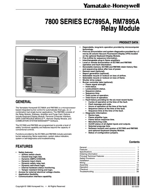
This Honeywell RM7895A1014 Installation Manual guide follows the 28-page document honeywellmanual.com lists under that name: form 65-0205, marked “PRODUCT DATA”, “Copyright © 1996 Honeywell Inc.” and titled “7800 SERIES EC7895A, RM7895A RELAY MODULE”. Installation begins on page 9; troubleshooting starts on page 26.
One naming point first. The body text never prints RM7895A1014. It says RM7895A, while the only “1014” in the document belongs to the Q7700A1014 network interface unit. Treat the listing title as the catalog name and look for RM7895A on the label.
The manual calls the product “a microprocessor based integrated burner control for automatically fired gas, oil, or combination fuel single burner applications”, and assembles it from four parts: “The RM7895 consists of the Relay Module. Subbase, Amplifier and Purge Card.”
Download Honeywell RM7895A1014 Installation Manual (PDF)
Table of Contents
What the Manual Covers
The contents page runs General, Features, Specifications, Ordering Information, Principal Technical Features, Safety Provisions, Installation (page 9), Wiring (11), Assembly (14), Operation (17), Checkout (20) and Troubleshooting (26). The EC7895A shares every chapter; it is the 200 Vac version and carries its own terminal table, Table 1B.
The feature list opens with safety: airflow switch check, closed loop logic test, dynamic AMPLI-CHECK, dynamic input check, dynamic safety relay test, dynamic self-check logic, internal hardware status monitoring, and tamper resistant timing and logic. Five LEDs report the sequence: “POWER, PILOT, FLAME, MAIN and ALARM.” Nonvolatile memory retains “history files and sequencing status after loss of power.”
The optional Keyboard Display Module adds a “2 row by 20 column Vacuum Fluorescent Display (VFD)” for first-out annunciation. The system “distinguishes 43 modes of failure and detects and annunciates difficult-to-find intermittent failures.”
Electrical and Environmental Ratings
The RM7895A supply is “100 Vac (+10/-15%), 50 or 60 Hz (+/- 10%).” Power dissipation is “10W maximum”, the load ceiling is “2000 VA maximum connected load to 7895 Assembly.”, and fusing is “20A maximum, type FRN or equivalent”. The EC7895A takes 200 Vac; Table 1B covers its terminals.
The environmental block gives operating −40 °F to 140 °F and storage −60 °F to 150 °F, plus “85% RH continuous, noncondensing” and a “0.5G environment.” With its dust cover the module weighs “1 pound 15 ounces, unpacked.”
Approvals are split by model: “RM7895A: Underwriters Laboratories Inc. listed: File no. MP268, Guide no. MCCZ. Factory Mutual approved.” The EC7895A entry lists Factory Mutual only. Dimensions sit in Fig. 1 and Fig. 2 rather than in the text.
RM7895A Terminal Ratings
Table 1A is headed “RM7895A Terminal Ratings.” It runs from the two ground entries through terminal 22; terminals 12 to 21 print “Unused” on every row and are omitted here, with the warning repeated below.
| Terminal | Description | Rating |
|---|---|---|
| G | “Flame Sensor Ground Earth” | — |
| G | “Earth Ground” | — |
| 2 | “L2(N)”, “Line Voltage Common” | — |
| 3 | Alarm | “100 Vac, 1A pilot duty.” |
| 4 | Burner Motor | “100 Vac, 9.8 AFL, 58.8 ALR (inrush).” |
| 5 | Line Voltage Supply (L1) | “100 Vac (+10/-15%), 50 or 60 Hz (+/- 10%).” |
| 6 | Burner Controller and Limits | “100 Vac, 1 mA.” |
| 7 | Airflow Interlock | “100 Vac, 9A.” |
| 8 | Pilot Valve/Ignition | “100 Vac, 4.5A ignition and 50VA pilot duty.” |
| 9 | Main Fuel Valve | “100 Vac, 2A pilot duty.” |
| 10 | Ignition | “100 Vac, 4.5A ignition.” |
| F(11) | Flame Sensor | “60 to 220 Vac, current limited.” |
| 22 | Shutter | “100 Vac, 0.5A” |
Terminals 12 to 21 are “Unused”, and the wiring figures warn “DO NOT CONNECT ANY WIRES TO UNUSED TERMINALS.”
What a Complete Installation Needs
Three items are required besides the RM7895A relay module: “Plug-in Flame Signal Amplifier, see Table 2. Plug-in Purge Timer Cards: Selectable ST7800A, two seconds to 30 minutes. Q7800A or Q7800B.”
Table 2 sorts amplifiers by detection method and colour: rectification (green) R7847A, AMPLI-CHECK R7847B and self-check R7847C; infrared (red) R7848A and R7848B; ultraviolet (purple) R7849A and R7849B, plus the self-checking R7861A and R7886A. “Make sure the correct combination of amplifier and flame detector(s) is used.”
One footnote matters on continuously firing equipment: “The C7012A,C, C7027, C7035 and C7044 Flame Detectors should be used only on burners that cycle on-off at least once every twenty-four hours.” The subbase choice is “Q7800A for panel mount or Q7800B for wall or burner mount”, and “PURGE is determined by the ST7800A Purge Card selected.”
Mounting the Q7800A Subbase
Mount the subbase in any position except horizontally with the bifurcated contacts pointing down. The standard vertical position is recommended; any other position decreases the maximum ambient temperature rating.
Choose a wall, burner or panel location; the Q7800 can sit in the control cabinet. Leave service clearance for the module, cover, amplifier and probes, then use the back of the subbase as a template for four no. 6 screws.
Mount the module vertically, or horizontally with the knife blade terminals pointing downward. On a Q7800A it must be inside an electrical enclosure. Tuck wiring against the back of the subbase, align the four L-shaped corner guides, and use “a plug-in motion rather than a hinge action.”
Site limits are strict: “The EC7895 or RM7895 is not designed to be weather tight.” Outdoors it needs an approved weather-tight enclosure. Condensing moisture can cause a safety shutdown, and vibration must not exceed 0.5G continuous.
Wiring Rules and Limits
Start with the disconnect: “Disconnect the power supply before beginning installation to prevent electrical shock and equipment damage.” More than one power disconnect may be involved. Use “no. 14, 16, or 18 copper conductor (TTW60C or THW75C or THHN90C) 600 volt insulation wire for all Line Voltage terminals.”
Grounding gets its own paragraph: the earth wire must be able to blow the 20A fuse in an internal short, the path must be low impedance, and wide straps or brackets are preferred over leadwires.
For flame detector wiring, “Do not run high voltage ignition transformer wires in the same conduit with the flame detection wiring.” Keep sensor leads short, because “The maximum permissible leadwire length depends on the type of flame detector, leadwire and conduit.” Control and airflow interlock leads top out at 300 feet.
One discrepancy deserves a meter. Fig. 7 labels the supply “120V, 50/60 Hz POWER SUPPLY.” while page 2 rates the module at “100 Vac (+10/-15%)”, which tops out at 110 Vac. Check the panel against Table 1A first.
Complete the static checkout with the module off the subbase: “After checking all wiring, perform this checkout before installing the EC7895 or RM7895 on the subbase.”
Purge Card, Cover and Amplifier
The ST7800A purge card goes in after the dust cover or display module comes off. Pull upward on the plastic support cover to release the old card, confirm the replacement has the desired timing, insert it into the opening, refit the cover, restore power, and run at least one complete cycle.
For the amplifier, disconnect power, align the circuit board edge connector with the keyed receptacle, “Ensure the amplifier nameplate faces away from the Relay Module”, push until fully inserted, then seat it toward the retaining clasp. The dust cover aligns by its two interlocking ears and slots. “Perform all required checkout tests.”
Flame detector installation defers to the detector instructions, with one rule repeated here: “Keep the flame signal leadwires as short as possible from the flame detector to the wiring subbase.”
Sequence, Jumpers and the LEDs
Power-up starts a ten-second INITIATE period. If line voltage or frequency falls outside +10/−15% or ±10%, the module holds, and “If the condition is not corrected and the hold condition exists for four minutes, the RM7895 locks out.”
STANDBY waits for a call for heat and the correct state on the burner switch, limits and monitored circuits. PREPURGE is selectable from two seconds to 30 minutes, with the blower motor output on terminal 4. The airflow interlock must close ten seconds into PREPURGE or within the purge card timing.
During the pilot trial, terminals 8 and 10 energize. Flame must prove within the 4 or 10 second PFEP; then ignition drops out and terminal 9 powers the main fuel valve. A flameout brings lockout or recycle “within .8 or 3 seconds, depending on the Flame Failure Response Time (FFRT) of the amplifier.”
| Device | Initiate | Standby | Purge | Pilot | Main |
|---|---|---|---|---|---|
| EC7895A/RM7895A | 10 sec. | * | ** | 4 or 10 sec. | No |
* STANDBY and RUN can be infinite. ** PURGE is set by the ST7800A card. The main column prints “No”.
Three site-configurable jumpers set the behaviour; clip them with side cutters and remove the resistors, which the manual says enhances safety.
| Jumper | Function | Intact | Clipped |
|---|---|---|---|
| JR1 | Pilot Flame Establishing Period | 10 seconds | 4 seconds |
| JR2 | Flame Failure Action | Recycle | Lockout |
| JR3 | Airflow Switch (ILK) Failure | Recycle | Lockout |
The green POWER LED blinks every four seconds while the hardware runs correctly; PILOT, FLAME, MAIN and ALARM report the rest.
Checkout and Flame Signal
Table 4 holds seven static tests. They jumper the subbase and read voltage to L2: 5-L2 for line voltage, 6-L2 for limits, 4-5 to start the burner motor and see 7-L2 within ten seconds, 5-10 for ignition, 5-8 for pilot, 5-9 for the main valve, and 5-3 for the alarm. Close all manual fuel shutoff valves first.
Do not megger the installed control: “Do not perform a dielectric test with the EC7895 or RM7895 installed.”
The flame signal floor is 1.25 Vdc, with 5.0 Vdc expected at the Keyboard Display Module or at a 1M ohm/volt meter. “Measure the flame signal at the appropriate times defined in the following checkout tests.” Read at the + and − (Com) jacks on the 0 to 10 Vdc range.
Five safety shutdown tests close the section: an airflow interlock closed during PREPURGE, PILOT IGN, MAIN IGN or RUN; a simulated flame 40 seconds after STANDBY entry or 30 seconds into PREPURGE; failed pilot ignition; failed main ignition; and loss of flame during RUN. “Safety shutdown occurs.” each time.
On replacement: “If an EC7895 or RM7895 is replaced with a lower or higher functioning 7800 SERIES Relay Module, the burner will not sequence unless wiring changes are made.”
RM7895A Troubleshooting
RM7895A troubleshooting starts at the ALARM LED and, if fitted, the Keyboard Display Module. “First-out Annunciation reports the cause of a safety shutdown or identifies the cause of a failure to start or continue the burner control sequence with text and numbered code via the optional Keyboard Display Module.” Self-diagnostics separate field faults from internal ones.
Nonvolatile memory keeps “Historical Information for the six most recent lockouts”, with the cycle, hour, fault message and burner status at the time of each fault. Status messages are STANDBY, PRE-PURGE, PILOT IGN, MAIN IGN and RUN.
Display holds are STANDBY HOLD F/G (flame detected), STANDBY HOLD T7 (closed airflow interlock), PURGE HOLD F/G and PURGE HOLD T7. A flame that does not clear within 40 seconds in STANDBY locks the RM7895 out; either purge hold locks out after 30 seconds.
Reset with the pushbutton, or remotely through a Keyboard Display Module, DATA CONTROLBUS MODULE, Extension Cable Assembly or Remote Reset Module. “A power-up reset causes an electrical reset of the EC7895 or RM7895 but does not reset a lockout condition.” For deeper diagnostics the manual points to “the 7800 SERIES System Annunciation Diagnostics and Troubleshooting, form 65-0118.”
FAQ
Does the manual print the model number RM7895A1014?
No. The body prints RM7895A; the only “1014” is inside the Q7700A1014 part number on page 5. The listing title carries the longer number.
What supply voltage does the RM7895A require?
“100 Vac (+10/-15%), 50 or 60 Hz (+/- 10%).” Fig. 7 labels its supply “120V, 50/60 Hz POWER SUPPLY.” which sits outside that band, so verify the panel voltage before wiring.
Which subbase and purge card fit the RM7895A?
“Q7800A for panel mount or Q7800B for wall or burner mount.” The purge card is a “Selectable ST7800A, two seconds to 30 minutes”, and its timing sets the PREPURGE period.
How long are INITIATE, PREPURGE and the pilot trial?
INITIATE lasts ten seconds if the supply stays within tolerance. PREPURGE runs from two seconds to 30 minutes, set by the ST7800A card. The pilot flame establishing period is 10 seconds with JR1 intact and 4 seconds with JR1 clipped.
What flame signal is acceptable?
At least 1.25 Vdc, and 5.0 Vdc expected at the Keyboard Display Module or a 1M ohm/volt meter. Measure at the amplifier’s + and − (Com) jacks on the 0 to 10 Vdc range.
How do I clear a lockout?
Press the reset pushbutton, or use a remote reset if one is wired. A power-up reset does not clear a lockout. The module retains the six most recent lockouts, with cycle, hour, fault message and burner status.