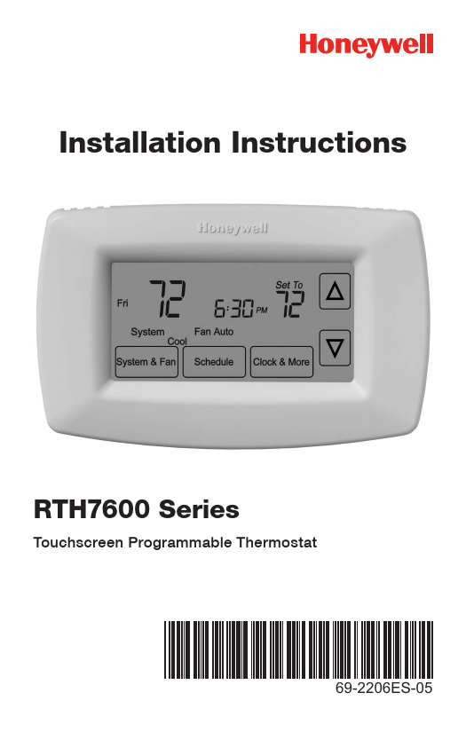
The Honeywell Touchscreen Programmable Thermostat RTH7600 Series Installation Instructions walk through eleven numbered steps, from shutting off power to matching the thermostat to your equipment. This page follows that document, 69-2206ES—05, which is linked below. It covers mounting, wiring for conventional and heat pump systems, the function settings the installer menu exposes, and the eight faults the manual itself lists. Schedule programming is not part of this booklet; the only reference to the Operating Manual is on the setup page for Smart Response Technology.
Download the Honeywell RTH7600 Series Installation Instructions (PDF)
Download the official Honeywell RTH7600 Series Installation Instructions (PDF)
Table of Contents
- What These Installation Instructions Cover
- Compatibility and Power Requirements
- Parts the Manual Names
- Step-by-Step Installation (Steps 1 to 11)
- Wiring: Conventional and Heat Pump Terminals
- Advanced Installation: Function Settings
- Troubleshooting
- Specifications
- Frequently Asked Questions
What These Installation Instructions Cover
The booklet is an installer document, not a homeowner guide. Its own contents page divides the work into two halves. The first half is the eleven numbered steps on pages 1 to 11. The second half is called Advanced Installation and runs from page 13 to page 26.
Advanced Installation breaks down like this:
- Thermostat setup, pages 13 to 20. Entering setup options, the date, system type, changeover mode, temperature format, daylight saving time, the filter reminder, Smart Response Technology, and the clock format.
- Wiring, pages 21 to 23. Alternate wiring for conventional systems on page 21, the heat pump connection procedure on page 22, and alternate wiring for heat pumps on page 23. The two alternate charts are for old thermostats whose terminal letters do not match the new one.
- Troubleshooting, pages 24 and 25. Eight symptom-and-action entries.
- Customer assistance, page 26.
Page numbers on this page are the ones printed on the sheet. The English section of the PDF file begins on file page 3, so printed page 13 is file page 15.
The booklet’s introduction page states the two principles behind the sequence: the thermostat “works with virtually all System Types” and “is preset for the most common system.”
Compatibility and Power Requirements
One sentence on page 11 decides whether the RTH7600 Series belongs on your wall at all. The thermostat “works on 24 volt or 750 mV systems. It will NOT work on 120/240 Volt systems.”
Page 11 also splits the work by system type, and the split is the reason some installations stop at step 11 while others continue into the advanced pages:
- Single Stage Heat and Cool. The manual’s response is “Congratulations, you’re done!”
- Multistage Heat and Cool, heat pump without backup heat, heat pump with backup heat, heat only, or cool only. These continue into the advanced pages, which the booklet describes as the step that matches the thermostat to the system type.
The same page defines a heat pump for readers who are unsure: “an air conditioner that provides cooling in the summer, and also runs in reverse in the winter to provide heating.” If the system type is still unclear, the manual directs the reader to the toll-free line at 1-800-468-1502.
What the terminal strip accepts
The conventional strip carries eight positions: R, RC, W, Y, G, C, W2 and Y2. The heat pump strip carries nine: R, RC, O/B, Y, G, C, L, E and Aux. The extra positions on each side are what separate a single-stage installation from a multistage one, and the function table later in this page is where those positions get declared.
Parts the Manual Names
The booklet references only what the installation actually touches:
- Mounting screws and anchors, described in step 5 as “the included screws and anchors.”
- Wire labels, described in step 3 as “the supplied wire labels.”
- Two AA alkaline batteries, installed in step 7, which also has you remove a tab.
- A small piece of wire, called for on the heat pump pages when the E and Aux terminals do not each have a conductor connected.
A screwdriver is required by the heat pump wiring steps, which say to “loosen screws, insert wires into hole, then tighten screws.” Two drill bits appear in step 5: 3/16-in. for drywall and 3/32-in. for plaster.
Step-by-Step Installation (Steps 1 to 11)
The eleven steps in the booklet run in one direction, with one branch at the end. Steps 1 to 9 are physical work at the wall. Steps 10 and 11 are done on the screen with the power back on.
Step 1: Turn off power to the heating and cooling system
The first page is a single instruction and a note. The instruction is to cut power to the heating and cooling system. The note is for readers who have already worked through the Quick Start Guide and only need to match the thermostat to a system type: that reader is sent straight to page 13.
Step 2: Remove the old thermostat
The old thermostat comes off, but its wallplate stays on the wall with the wires still attached. The page carries a warning about the old unit: if it holds a sealed tube containing mercury, the back cover of the booklet gives the disposal instructions.
Step 3: Label the wires with the supplied tags
Each conductor gets a tag as it is disconnected. The page adds one caution that matters more than it looks: “Wire color may not match labels.” Colour is not the identifier here. The tag is.
Step 4: Separate the wallplate from the new thermostat
The new wallplate arrives fitted to the back of the thermostat body and has to come off before it can be mounted. Step 4 is that separation and nothing else.
Step 5: Mount the new wallplate
The wallplate goes on with the included screws and anchors. The booklet prints two pilot-hole sizes on the same page:
- 3/16-in. holes for drywall.
- 3/32-in. holes for plaster.
Step 6: Connect the wires
The entire instruction is four words: “Simply match wire labels.” Each tag goes to the terminal of the same letter, and the wires are inserted into the holes and the screws tightened.
One exception sits under the drawing. Remove the metal jumper between R and Rc if both terminals will carry a wire. The full jumper rules are on page 21 and are covered under Wiring below.
Two routing notes appear on the page. A heat pump system sends the reader to pages 22 and 23. Terminal letters on the old thermostat that do not match send the reader to page 21.
Step 7: Install the batteries
Two AA alkaline batteries go into the back of the thermostat, and a tab is removed. The drawing labels the two locations as “Back of thermostat” and “Remove tab.”
Step 8: Install the thermostat onto the wallplate
The body pushes onto the mounted wallplate. Step 8 is that single action.
Step 9: Turn the power back on
Power returns to the heating and cooling system. Everything after this point happens on the screen.
Step 10: Set the time and date
The screen presents four values in a fixed order, with the arrow buttons changing the value and the NEXT button moving to the next one:
- Press the up or down arrow to set the month, then press NEXT.
- Press the arrow buttons to set the day, then press NEXT.
- Press the arrow buttons to set the year, then press DONE.
- Press the arrow buttons to set the time, then press DONE to save and exit.
Step 11: Match the thermostat to your system type
This step is a branch, not a task. A single-stage heat and cool system finishes here. Every other system type continues into Advanced Installation, where function 0170 declares what the thermostat is connected to.
If the date and time were already set on page 10, the advanced section notes that the reader can press NEXT through to function 0170 and go directly to the system type setting.
Wiring: Conventional and Heat Pump Terminals
Two drawings cover the terminals, one for each system family. In both cases the rule is the same as step 6: the tag on the wire and the letter on the terminal have to match.
Conventional terminal strip
| Terminal | Function |
|---|---|
| R | Power side |
| RC | Power side, jumpered to R by the metal jumper |
| W | Heat |
| Y | Cool |
| G | Fan |
| C | Common |
| Y2 | Second cooling stage |
| W2 | Second heating stage |
The letters in the left column are printed on the thermostat. The function words beside them are added here to make the strip readable; the booklet prints the letters only.
Heat pump terminal strip
| Terminal | Function |
|---|---|
| R | Power side |
| RC | Power side, jumpered to R |
| O/B | Changeover valve |
| Y | Compressor |
| G | Fan |
| C | Common |
| L | Service indicator |
| E | Emergency heat |
| Aux | Auxiliary heat |
The same note applies to this table: the letters are the manual’s, the function words are added here. The heat pump page adds a fourth wiring step beyond matching, inserting and tightening: if E and Aux do not each have a wire connected, a small piece of wire joins them to each other. A fifth note says to push any excess wire back into the wall opening.
Alternate wiring when the old letters do not match
Older thermostats carry lettering this one does not. Page 21 has the conventional chart and page 23 has the heat pump chart. Both are read the same way: find the old label on the right, land the wire on the terminal at the left.
Conventional systems, page 21:
| Old thermostat label | Terminal on the RTH7600 |
|---|---|
| Rc or R | Rc |
| R, RH, 4, or V | R |
| W, W1, or H | W |
| Y, Y1, or M | Y |
| G or F | G |
| C, C1, X, or B | C |
| Y2 | Y2 |
| W2 | W2 |
Heat pump systems, page 23:
| Old thermostat label | Terminal on the RTH7600 |
|---|---|
| Rc or R | Rc |
| R, V, or VR | R |
| O, H, or B | O/B |
| Y, Y1, or M | Y |
| G or F | G |
| C, X, or B | C |
| L or F | L |
| E, X, or X2 | E |
| Aux, W, W1, or W2 | Aux |
The R and Rc jumper
A metal jumper connects R and Rc on the terminal strip, and step 6 says to remove it if both terminals will carry a wire. Page 21 gives the three cases in full:
- Both R and Rc wires present. Remove the metal jumper and connect both.
- Old thermostat had R and RH wires. Remove the metal jumper, connect the R wire to the Rc terminal, and connect the RH wire to the R terminal.
- No second power wire. Leave the jumper in place.
On a heat pump the instruction reverses: page 23 says to leave the metal jumper in place, connecting R and Rc.
Where the manual stops and calls a contractor
Three conditions on page 23 end the installation. Each one is a stop, not a caution:
- An old thermostat with both V and VR wires.
- An old thermostat with Y1, W1 and W2 wires.
- Separate O and B wires, when another wire already occupies the C terminal. The manual’s instruction for the O and B case is to attach the B wire to the C terminal, and to stop only if C is already taken.
One further rule ties two terminals together: if the L terminal is used, the C terminal must have a wire, and the manual directs the reader to a contractor when there is no C wire.
Advanced Installation: Function Settings
Everything from page 13 onward is reached through the setup menu. The menu holds fifteen functions, numbered in hundreds, and the numbers are printed on the screen rather than in the booklet’s headings.
How to open the setup menu
- Press and release the left button.
- Press and hold the center button until the screen changes, which the manual puts at approximately five seconds.
Inside the menu, the arrow buttons change the value that is showing, NEXT moves to the next function number, and DONE saves and exits. The booklet notes that some functions may not appear at all, depending on selections already made. That is why a single-stage installation sees a shorter menu than a heat pump.
Function table
| Function | What it sets | Options |
|---|---|---|
| 0120 | Year, first two digits | 20 = year 20xx · 21 = year 21xx |
| 0130 | Year, last two digits | 01 to 99 |
| 0140 | Month | 01 to 12 |
| 0150 | Date | 01 to 31 |
| 0170 | System type | 1 = heat and cool, gas, oil or electric with central air · 2 = heat pump without backup or auxiliary heat · 3 = heat only · 4 = heat only with fan · 5 = hot water heat only, no fan · 6 = cool only · 7 = heat pump with backup or auxiliary heat · 8 = two heat stages on W and W2, two cooling stages on Y and Y2 · 9 = two heat stages on W and W2, one cooling stage on Y · 10 = one heat stage on W, two cooling stages on Y and Y2 |
| 0180 | Heating fan control | 0 = gas or oil heat, system controls fan operation · 1 = electric heat, thermostat controls fan operation |
| 0190 | Heat pump changeover valve | 0 = cooling changeover valve, for an O wire on O/B · 1 = heating changeover valve, for a B wire on O/B |
| 0240 | Heating cycle rate | 5 = gas or oil furnace under 90% efficiency · 9 = electric furnace · 3 = hot water system or gas furnace over 90% efficiency · 1 = gas or oil steam or gravity system |
| 0270 | Emergency heat cycle rate, heat pumps only | 9 = electric furnace · 5 = gas or oil furnace under 90% efficiency · 3 = hot water system or gas furnace over 90% efficiency · 1 = gas or oil steam or gravity system |
| 0300 | Manual or auto changeover | 0 = manual, Heat, Cool and Off · 1 = automatic, Heat, Cool, Auto and Off, which turns on heat or cool from room temperature and keeps a minimum 3°F difference between the heat and cool settings |
| 0320 | Temperature format | 0 = Fahrenheit · 1 = Celsius |
| 0330 | Daylight saving time | 0 = off, no adjustment · 1 = on, for areas that do not use the 2007 DST calendar · 2 = on, for areas that use the 2007 DST calendar |
| 0500 | Furnace filter change reminder | 0 = off · 1 = 10-day run time, about 1 month · 2 = 30 days, about 3 months · 3 = 60 days, about 6 months · 4 = 90 days, about 9 months · 5 = 120 days, about 1 year · 6 = 365 days, about 3 years |
| 0530 | Smart Response Technology | 1 = on · 0 = off |
| 0640 | Clock format | 12 = 12-hour clock · 24 = 24-hour clock |
The booklet defers one function to another document: function 0530 refers the reader to the Operating Manual for an explanation of Smart Response Technology. The setup pages end with DONE to save and exit.
Troubleshooting
The manual’s troubleshooting pages are a two-column list of eight entries, running across pages 24 and 25. Symptom wording and the action column below follow that list. The cause column is added here, because the manual prints actions without stating a cause.
| Symptom | Likely cause | What the manual says to do |
|---|---|---|
| Display is blank | The batteries are missing or not seated | Make sure fresh AA alkaline batteries are properly installed (see page 7). |
| Cannot change system setting to Cool | The system type does not include cooling | Check Function 0170: System Type to make sure it is set to match your heating and cooling equipment (see page 16). |
| Fan does not turn on when heat is required | The fan control setting does not match the heating equipment | Check Function 0180: Heating Fan Control to make sure it is set to match your heating equipment (see page 17). |
| Heating system is running in cool mode | The system type is declared incorrectly | Check Function 0170: System Type to make sure it is set to match your heating and cooling equipment (see page 16). |
| Red light is on | The thermostat is in Emergency Heat mode, or it is not and something else is wrong | If thermostat is in Emergency Heat mode the red light is normal. It shows that the thermostat is in emergency heat mode. If thermostat is not in Emergency Heat mode, contact a qualified service contractor for repair. |
| Heating or cooling system does not respond | The system switch position, the setpoint, or power at the equipment | Press SYSTEM to set system to Heat. Make sure the temperature is set higher than the Inside temperature. Press SYSTEM to set system to Cool. Make sure the temperature is set lower than the Inside temperature. Check circuit breaker and reset if necessary. Make sure power switch at heating & cooling system is on. Make sure furnace door is closed securely. Wait 5 minutes for the system to respond. |
| “Wait” appears on the screen | Compressor protection is holding the compressor back | Compressor protection feature is engaged. Wait 5 minutes for the system to restart safely, without damage to the compressor. |
| Heat pump issues cool air in heat mode, or warm air in cool mode | The changeover valve setting is inverted | Check Function 0190: Heat Pump Changeover Valve to make sure it is properly configured for your system (see page 17). |
Four of the eight entries route back to a function number, which is the pattern worth noticing: 0170 appears twice, 0180 once, and 0190 once. After mounting and wiring, most faults on this thermostat are settings that were left on the wrong value rather than failed parts.
Page 26 of the booklet gives the escalation path. Assistance is at http://yourhome.honeywell.com or on the toll-free line, 1-800-468-1502. The same number appears on the inside front cover, with the note to call before returning the thermostat to the store, and again on the step 6 page for wiring assistance.
Specifications
- Model line: RTH7600 Series, touchscreen programmable thermostat.
- Document: 69-2206ES—05, revision 04-11, printed in the U.S.A., © 2011 Honeywell International Inc.
- Power source: two AA alkaline batteries, installed at step 7.
- System voltage: 24 volt or 750 mV. Not for 120/240 volt systems.
- Conventional terminals: R, RC, W, Y, G, C, Y2, W2.
- Heat pump terminals: R, RC, O/B, Y, G, C, L, E, Aux.
- System types: ten options at function 0170, covering single-stage heat and cool, heat pump with and without backup heat, heat only, hot water heat only, cool only, and three multistage combinations.
- Changeover: manual or automatic, set at function 0300. Automatic mode keeps a minimum 3°F between the heat and cool settings.
- Compressor protection: a five-minute wait is printed in the troubleshooting list and applies to the “Wait” message.
- Filter reminder intervals: 10, 30, 60, 90, 120 or 365 days of run time, set at function 0500.
- Warranty: one year from the date of purchase, excluding the battery.
- Operating caution: to avoid possible compressor damage, do not run the air conditioner when the outside temperature drops below 50°F (10°C).
Frequently Asked Questions
Where can I get the RTH7600 Series installation instructions as a PDF?
The download link at the top and bottom of this page opens the manufacturer PDF for this document. It holds the eleven numbered steps, the terminal drawings for conventional and heat pump systems, the alternate wiring charts, and the fifteen-function setup table.
What batteries does the RTH7600 Series take?
Two AA alkaline batteries, installed in step 7 on the back of the thermostat, and the step also has you remove a tab. The troubleshooting list sends a blank display back to that same page.
Does the RTH7600 need a C wire?
There is a C position on the strip, and step 7 installs two AA alkaline batteries as the supply the booklet calls for. On a heat pump the C terminal matters in one case. If the L terminal is used, the manual says the C terminal must carry a wire. It sends you to a contractor when there is no C wire.
Why will the thermostat not switch to Cool?
Function 0170, System Type, is probably set to a type that has no cooling. The manual’s own answer is to check that function against your equipment. The same function is the manual’s answer when the heating system runs in cool mode.
What does a Wait message on the screen mean?
Compressor protection is engaged. The manual says to wait 5 minutes for the system to restart safely, without damage to the compressor. Nothing needs resetting.
How do I open the installer setup menu?
Press and release the left button, then press and hold the center button until the screen changes, which takes about five seconds. The arrows change a value, NEXT moves to the next function number, and DONE saves and exits.
Can the RTH7600 Series control a two-stage system?
Yes. The strip carries W2 and Y2, and function 0170 offers three multistage options: two heat stages with two cooling stages, two heat stages with one cooling stage, and one heat stage with two cooling stages. A single-stage heat and cool system is the one type that finishes at step 11.
When should I stop and call a contractor instead?
The heat pump wiring page names three stops. They are an old thermostat with both V and VR wires, one with Y1, W1 and W2 wires, and separate O and B wires where the C terminal is already occupied. Use of the L terminal without a C wire is a fourth case the same page sends to a contractor.
Leave a Reply
You must be logged in to post a comment.