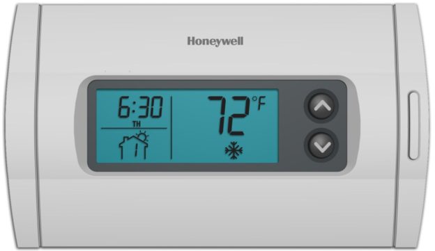
This installation guide walks through the job from identifying the existing wires to mounting the new thermostat and configuring the system.
The guide includes wiring diagrams for typical and less common installations, along with instructions for selecting the correct furnace type. It also explains the J2 jumper settings for gas, oil, and electric heating systems.
Download the official Honeywell RTH2310 Installation Guide (PDF)
Table of Contents
- What the RTH2310 Installation Guide Covers
- System Compatibility Check
- Removing the Old Thermostat
- Identifying the Wires
- Mounting the New Wallplate
- Connecting the Wires
- Setting the Furnace Type Jumper
- Batteries and First Power-Up
- Finishing Up and System Setup
- Frequently Asked Questions
What the RTH2310 Installation Guide Covers
The RTH2310 is a programmable thermostat, and this booklet deals only with putting it on the wall and powering it up. Printed page 1 states the purpose in a single line: the thermostat has been designed for fast and easy installation, and the reader is to follow the step-by-step instructions on the following pages. The ten-step list follows immediately below that line.
System Compatibility Check
Printed page 2 opens the work with step 1, identify system type, and lists the five systems the thermostat is compatible with:
- Gas, oil or electric furnace
- Central air conditioner
- A hot water system with or without pump
- A millivolt system
- A central heating and cooling system
A shaded box at the foot of the same page states the limit: the thermostat is not compatible with heat pumps or multi-stage systems.
The page also gives the support number for anyone unsure of the system type, 1-800-468-1502, and adds that the line handles any other questions too. The same number appears again on printed page 1 under the heading Do you need assistance?
Removing the Old Thermostat
Step 2 is two instructions. Turn the power off at the heating and cooling system, then remove the old thermostat while leaving the wallplate with the wires attached. The page repeats that last point as a callout: do not remove the wallplate yet. Step 3 is where the wallplate comes off, and only after the wires have been labelled.
Under the instructions sits a mercury notice. An old thermostat containing mercury in a sealed tube must not go in the trash. The local waste management authority gives the recycling and disposal instructions.
Identifying the Wires
Step 3 handles the wires, and the first paragraph sets out which ones are left out. Any wire that was not attached to the old thermostat, or that was attached to a terminal marked C or C1, will not be connected to the new thermostat. The bare metal end of each of those wires is to be wrapped in electrical tape so it cannot touch and short the others.
A warning with an exclamation mark closes the page, and it is about timing. The wires are to be disconnected and the old wallplate removed only after every wire has been labelled. To stop the wires dropping through the wall opening, the warning suggests wrapping them around a pencil.
Four callouts sit beside the two drawings. One says do not use non-connected wires, pointing at the loose ends in the upper drawing. Another says do not use C or C1 wires, pointing at the terminal marked C. A third says identify and label each wire, pointing at the lower drawing, where the wires carry tags. A fourth carries the labelling rule in capitals: ignore wire colours, and use the terminal screw designations to identify the wires. The upper drawing shows the old wallplate with terminals marked Y, W, G, R and C; the lower one shows the same wallplate with tags slipped over the wires.
Mounting the New Wallplate
Step 4 is four instructions. Remove the coverplate, loosen the screw, which stays captive on the wallplate, and remove the thermostat. The fourth covers the wall itself: mark and drill the appropriate mounting holes, or use the existing ones. Insert the plastic anchors, pass the wires through the opening in the wallplate, and secure it with the screws provided.
The guide names no drill size and no hole spacing, and it prints no dimensions for the wallplate. Those figures are not in this document, so they cannot be quoted from it.
Connecting the Wires
Step 5: The Typical Connection
The new wallplate carries five terminals, printed under the drawing as Rh, Rc, W, Y and G. Match each labelled wire with the terminal carrying the same letter. Loosen the terminal screws with a screwdriver, insert the wires and tighten them down, then push any excess wire back into the wall opening.
A jumper sits across Rh and Rc in the drawing, and a callout points at it: remove the jumper if you have both R and Rc wires. The drawing shows the incoming wires landing on Rc, W, Y and G, with the jumper linking Rh to Rc.
A grey box under the drawing takes the case where the labels do not match. If a wire does not match any terminal on the thermostat, the reader is sent to the next page.
Step 6: When the Labels Do Not Match
Printed page 7 carries the replacement table as a diagram. Each group of old terminal designations points down to the new terminal it belongs on:
| Wire label on the old thermostat | Terminal on the RTH2310 |
|---|---|
| C, X, B | Not used; wrap the bare end in electrical tape |
| R, RH, 4, V | Rh |
| Rc, R | Rc |
| W, W1, H | W |
| Y, Y1, M | Y |
| G, F | G |
Two numbered notes sit under the diagram. One repeats that C, X and B are not used and that their bare ends are to be taped. The other is the jumper rule, which is there because the letter R is printed under both the Rh and the Rc heading. Where wires reach both of those terminals, the jumper comes out, as shown on the previous page.
Setting the Furnace Type Jumper
Step 7 concerns a second jumper, J2, on the back of the thermostat. The page states the condition first: set J2 if a wire has been connected to the G terminal.
The page gives J2 two settings, HG and HE. HG is the position the thermostat ships in, and it is the one to leave alone on a gas or oil furnace. HE is the position for an electric furnace, and the jumper is moved there.
Batteries and First Power-Up
Step 8 is three instructions: pull out the battery cover, install the batteries as shown while observing the polarity, and reinstall the cover, which the page says produces a clicking sound. The drawing above the steps shows two cells marked AA LR6.
Once the cells are in, the thermostat runs a series of tests for about five seconds and then displays the actual temperature. The page adds a note about the reading: a temperature higher than the ambient one is normal while the thermostat is held in the hand. The ambient figure appears once the unit is on the wall. The same paragraph gives the starting setpoint, 70°F (21°C).
Finishing Up and System Setup
Step 9: Hanging the Thermostat
Mount the thermostat on the wallplate, tighten the screw, install the coverplate, and turn the power back on at the heating and cooling system. The third instruction carries a small drawing of a power switch marked ON and OFF.
Step 10: The Setup Menu
The setup menu is reached with the two arrow buttons. Pressing both the up and the down arrow together for three seconds enters or exits the menu. A brief press of both arrows together advances to the next function, and a single press of the up or the down arrow changes the setting.
Five functions are listed, and the default for each is printed in bold and underlined on the page:
| Function | Options | Setting as shipped |
|---|---|---|
| Temperature display | °C or °F | °F |
| Time display | 12 h or 24 h | 12 h |
| Early Start | On or Off | Off |
| Heating cycles per hour | 2, 3, 4, 5 or 6 | 4 |
| Cooling cycles per hour | 2, 3, 4, 5 or 6 | 4 |
Heating and cooling cycles share one menu position, and the footnote explains the split: use the system switch to switch between the two parameters. The two rows carry a flame symbol for heating and a snowflake for cooling.
One footnote converts the cycle numbers into minutes per cycle: 2 is 30 minutes, 3 is 20, 4 is 15, 5 is 12 and 6 is 10. The cooling lengths are the same. Another footnote maps the numbers to equipment for optimal heating control. 2 is for steam or gravity, 3 for hot water and 90%+ high-efficiency furnace, 4 for gas or oil, 5 as the alternate for gas or oil, and 6 for electric.
Early Start is listed without an explanation of its own. Its footnote points to page 3 of the Operating Manual.
Frequently Asked Questions
Will the RTH2310 work on a heat pump or a two-stage system?
No. Printed page 2 states that the thermostat is not compatible with heat pumps or multi-stage systems. The compatible list covers gas, oil or electric furnaces, central air conditioning, hot water systems with or without a pump, millivolt systems and central heating and cooling systems.
What if the letters on my wires do not match the terminals?
Printed page 7 maps them. R, RH, 4 and V go to Rh; Rc and R go to Rc; W, W1 and H go to W; Y, Y1 and M go to Y; G and F go to G. C, X and B are not used, and their bare ends are wrapped in electrical tape.
Do I have to change the J2 jumper?
Only if a wire is connected to the G terminal. HG is the position the thermostat ships in and is the one for a gas or oil furnace; HE is for an electric furnace.
Which cycles-per-hour setting should I pick?
The guide’s footnote maps them to equipment: 2 for steam or gravity, 3 for hot water and 90%+ high-efficiency furnaces, 4 for gas or oil, 5 as the alternate for gas or oil, 6 for electric. Both heating and cooling leave the setting at 4.